Condenser

A technology of condensing device and condensing box, which is applied in the direction of steam condensation, separation methods, chemical instruments and methods, etc. It can solve the problems that oil and gas cannot be condensed normally, and achieve the effect of saving manpower.

Active Publication Date: 2021-05-07
SHANGHAI WAIGAOQIAO SHIP BUILDING CO LTD
View PDF8 Cites 0 Cited by
  • Summary
  • Abstract
  • Description
  • Claims
  • Application Information

AI Technical Summary

Problems solved by technology

[0004] The technical problem to be solved by the present invention is to provide a condensing device in order to overcome the defect that the oil mist tank in the prior art cannot normally condense the oil gas in the oil mist due to high temperature

Method used


Image

  • Condenser
  • Condenser
  • Condenser

Examples


Embodiment Construction

[0032] In the following, the present invention will be more clearly and completely described by means of preferred embodiments in conjunction with the accompanying drawings, but the present invention is not limited to the scope of the described embodiments.

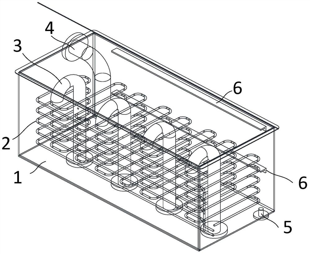
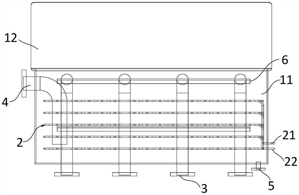
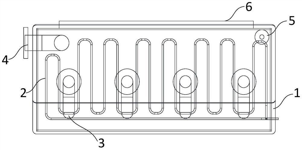
[0033] like Figure 1 to Figure 4 As shown, the present invention provides a condensing device, which includes a condensing box 1, a condensing coil 2 and a ventilation pipe. The condenser box 1 is a cuboid structure, which includes a box body 11 and a cover plate 12 , one side of the cover plate 12 is movably connected to the box body 11 . The cover plate 12 can be opened and closed around its connecting edge to facilitate maintenance by maintenance personnel, or to clean up oil stains in the condensation box 1 .

[0034] The condensing coil 2 is located in the condensing box 1 and is used for cooling the oil mist in the condensing box 1 . Condensate is installed inside the condensing coil 2 , and its inlet 21 and outl...


PUM


Abstract

The invention discloses a condensing device, which comprises a condensing box, a condensing coil and a ventilation pipe, the condensing box includes a box body and a cover plate, the condensing coil is located in the condensing box, and the condensing pan The inside of the pipe is equipped with condensate for cooling the oil mist in the condensing box, the ventilation pipe is located in the condensing box, and is used for making the oil mist enter and discharge the condensing box, the The condensing device also includes a relief valve for discharging the condensed oil in the condensing tank, the relief valve is a floating ball stop valve, and the relief valve is opened when the buoyancy of the condensed oil on the floating ball is greater than the gravity . The condensing device provided by the invention can keep the temperature in the condensing box relatively low, accelerate the cooling of the oil mist, and enable the oil and gas to separate out more and faster. The reciprocal position of the vent line and the condensate line also allows the oil mist to contact the condensate line more. When the condensed oil accumulates to a certain height, it can be automatically discharged through the relief valve, which saves manpower and is more convenient.

Description

technical field [0001] The invention relates to the field of oil mist discharge for ship work, in particular to a condensing device. Background technique [0002] The chimney area of ​​the ship is designed with an oil mist box, which is a separate cabinet. The fuel tank in the engine room area, the ventilation pipe of the lubricating oil tank and the ventilation pipe of the crankcase of the main engine will be collectively led into this cabinet. The working principle of the oil mist box is to rapidly expand and condense oil and gas. Before the oil and gas in the pipeline reach the oil mist box, it has passed a relatively long pipeline distance, and the temperature has dropped. The pipeline enters the oil mist tank, and the cross-sectional area of ​​the oil mist tank is much larger than the cross-sectional area of ​​the pipeline. At this time, the oil and gas expand rapidly. After the gas expands, the temperature drops again, and the oil and gas mixed in the air will be sepa...

Claims


Application Information

Patent Timeline
Patent Type & Authority Patents(China)
IPC IPC(8): B01D5/00
CPCB01D5/00
Inventor 徐江果杜文汇王兆强金春毅尹艳刘海冬张欢
Owner SHANGHAI WAIGAOQIAO SHIP BUILDING CO LTD
Why Eureka
Try Eureka