
Fitness equipment with massage pedals
A technology of fitness equipment and pedals, which is applied in kneading and massage equipment, massage auxiliary products, equipment for compressing reflex points, etc. It can solve problems such as single function, inability to provide customers with better user experience, and no massage structure to achieve functional more complete effect
- Summary
- Abstract
- Description
- Claims
- Application Information
AI Technical Summary
Problems solved by technology
Method used
Image

Examples
Embodiment Construction
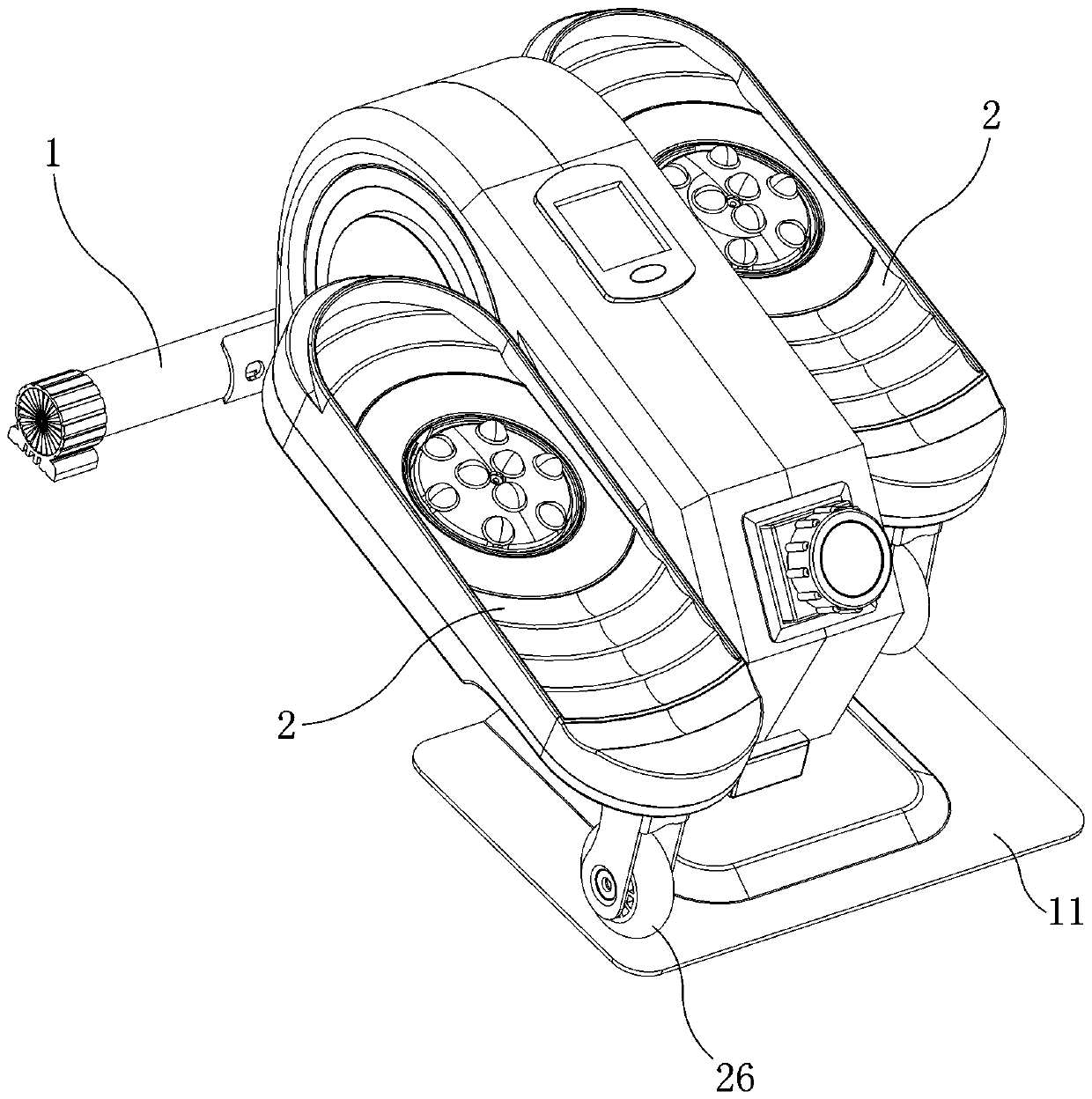
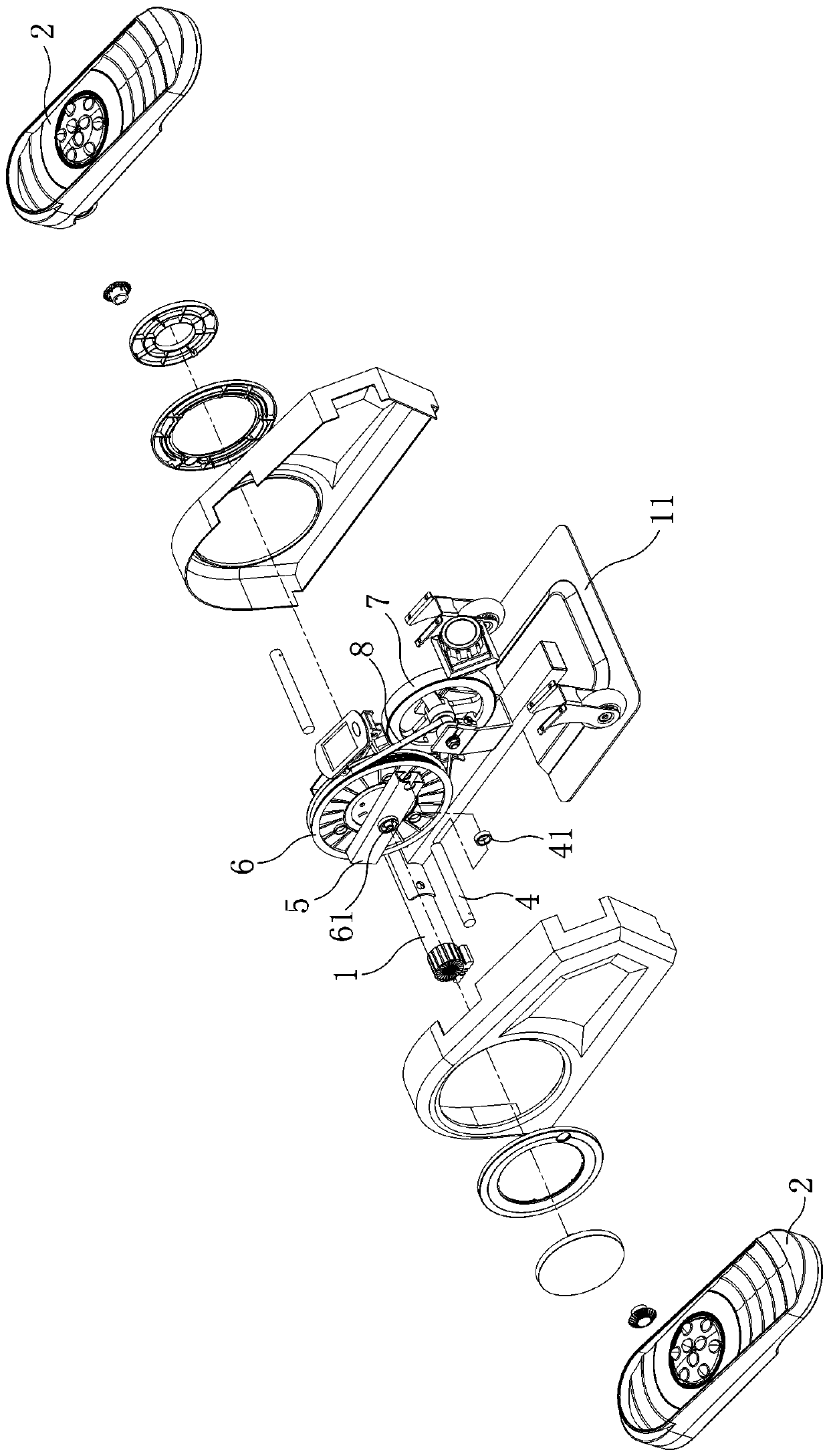
[0023] Such as figure 1 , figure 2 Shown, the present invention is a kind of fitness equipment with massage pedal, comprises frame 1, two pedals 2, two rotating shafts 4, flywheel swing arm 5, flywheel 6, damping wheel 7, belt 8.
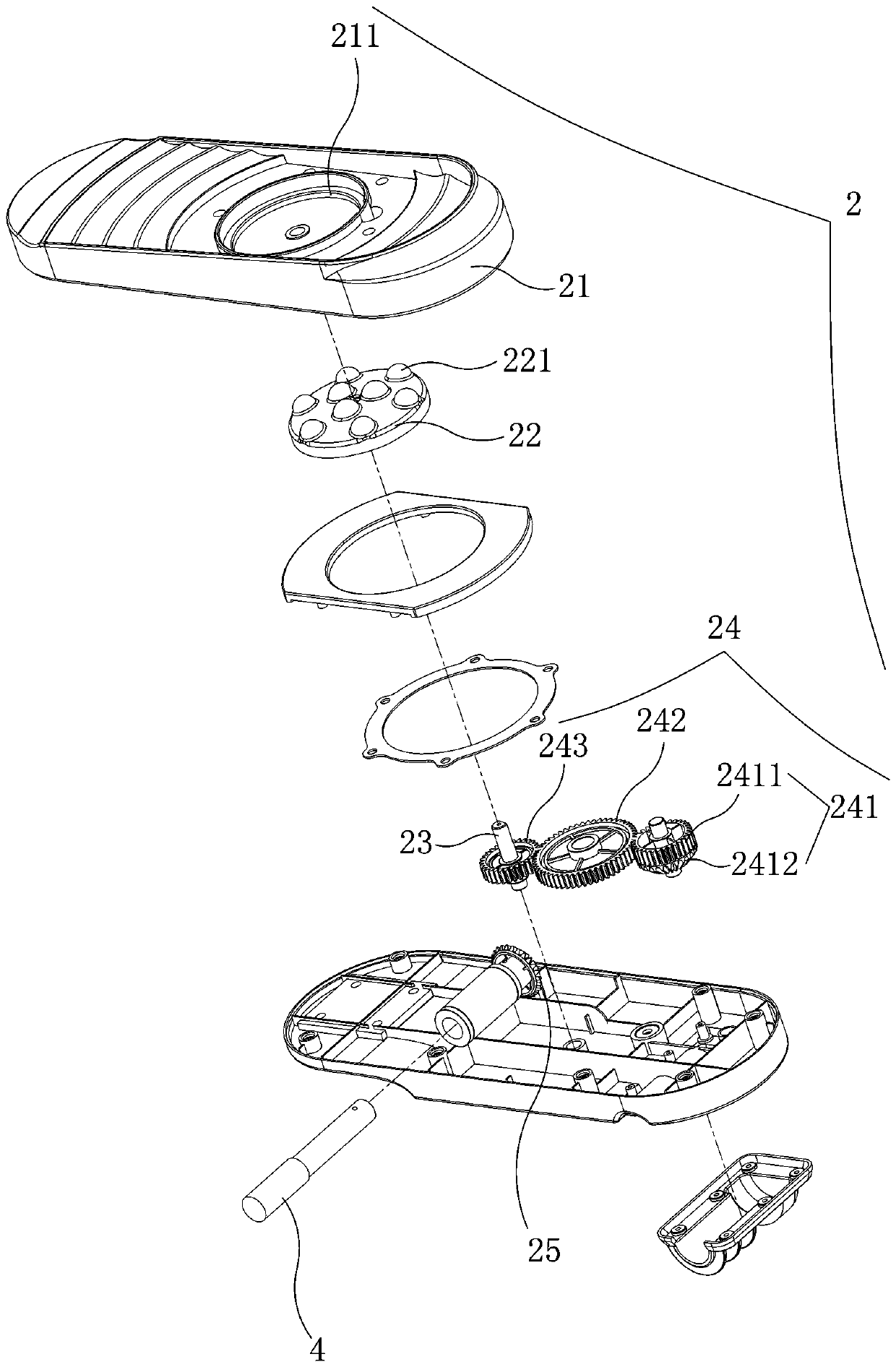
[0024] The two pedals 2 are symmetrically installed on the frame 1 and there is a massage mechanism on the pedals 2. The pedals 2 are connected with the rotating shaft 4, and the inner end of the rotating shaft 4 is rotatably connected with the outer end of the flywheel swing arm 5 through a bearing 41. The middle part of the flywheel swing arm 5 is fixedly sleeved on the outer end of the flywheel shaft 61, the flywheel shaft 61 is fixedly inserted on the flywheel 6 and the middle part of the flywheel shaft 61 is rotatably mounted on the frame 1 through a bearing, and the damping wheel 7 is rotatable It is installed on the frame 1, and the belt 8 is wound on the damping wheel 7 and the flywheel 6.
[0025] Such as Figure 3-Figure 5 Shown, is th...
PUM
 Abstract
Description
Claims
Application Information