

Air purification device of clean room
An air purification device and clean room technology, applied in air quality improvement, air conditioning system, space heating and ventilation, etc., can solve the problems of internal bacteria breeding, retention in the device, unfavorable use, etc., to reduce air humidity and avoid Effects of clogging and reducing bacteria
- Summary
- Abstract
- Description
- Claims
- Application Information
AI Technical Summary
Problems solved by technology
Method used
Image

Examples
Embodiment 1
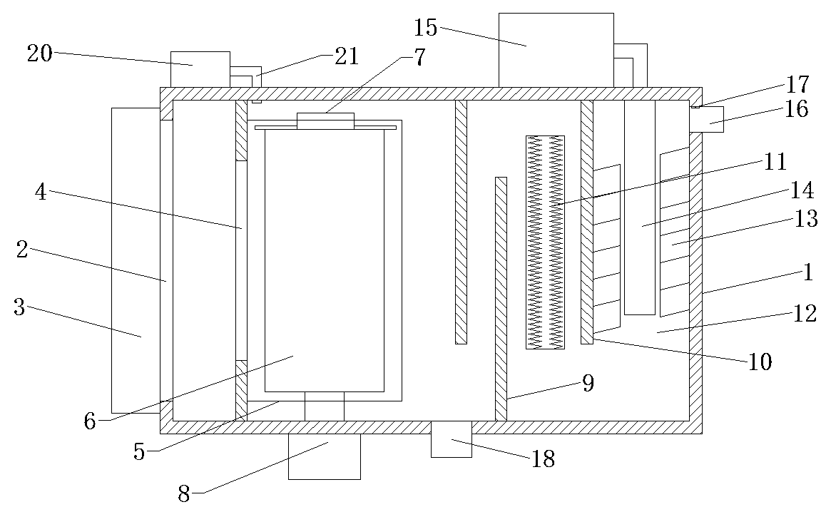
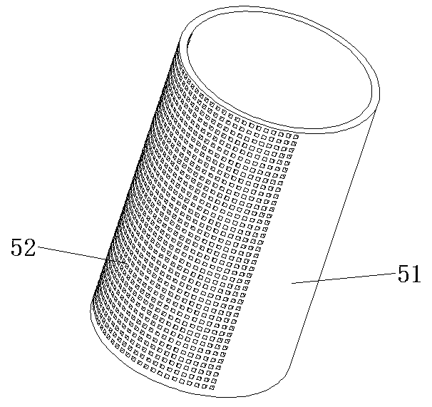
[0020] Please refer to the figure, in an embodiment of the present invention, an air purification device for a clean room includes a housing 1, an air inlet 2, an induced draft fan 3, an air outlet 4 and an air outlet pipe 16; the air inlet 2 is provided in the housing On the left side wall of 1, the induced draft fan 3 is installed on the air inlet 2, and the external air is sent into the housing 1 through the induced fan 3; a sealing plate facing the air inlet 2 is fixedly arranged in the housing 1, A vent 4 is opened on the sealing plate to make the air flow from the vent 4 to the right; a filter cylinder 5 is fixed on the right side of the vent 4, and the filter cylinder 5 is formed by a cylinder body 51 of a cylindrical structure and a cylinder body 51. The mesh plate 52 on one side is formed, and the mesh plate 52 faces the air vent 4, and the air is filtered through the filter cylinder 5, and impurities such as dust are filtered and left on the outer surface of the cylin...
Embodiment 2
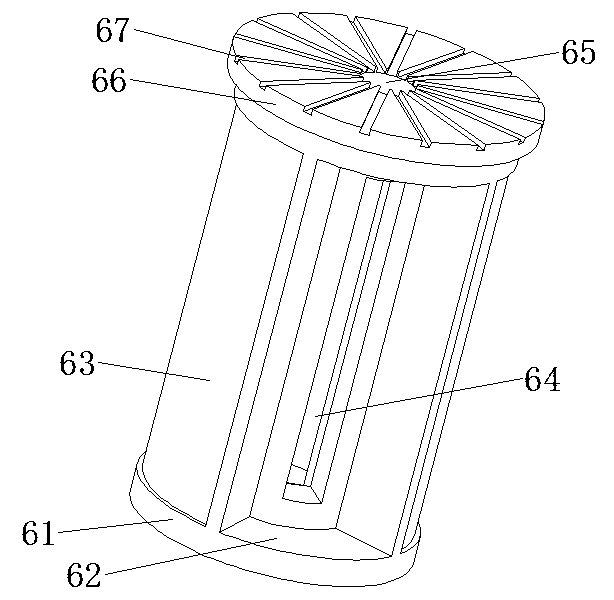
[0024] On the basis of Embodiment 1, a dispersing plate 66 is fixed on the top of the core 61. The dispersing plate 66 is a disc structure with a diameter larger than that of the core 61. On the upper surface of the dispersing plate 66, there are several Along the dispersion groove 67 in its radial direction, the outer end of the dispersion groove 67 passes through the edge of the dispersion plate 66, so that the water falling on the dispersion plate 66 can flow outwards along the dispersion groove 67, improving the washing range of water; A water pump 20 is fixedly installed on the top of the body 1, and the water pump 20 communicates with a water spray pipe 21 extending into the housing 1. The water spray pipe 21 is located directly above the mesh plate 52, and the water sprayed from the water spray pipe 21 falls on the On the dispersing plate 66, follow the dispersing plate 66 to make it evenly dispersed, especially can directly disperse water to the mesh plate 52, and wash ...
PUM
 Abstract
Description
Claims
Application Information