A multi-purpose stacking racking device and a multi-purpose stacking racking combination device

A combined device and multi-purpose technology, applied in the direction of packaging, containers, rigid containers, etc., can solve the problems that the cores cannot be stacked vertically directly, the number of layers and the size of the layer space cannot be adjusted arbitrarily, and the construction efficiency is low. Vertical support effect and installation stability, convenient storage and relocation and transportation, and excellent horizontal shear resistance

Active Publication Date: 2021-07-27
宋军
View PDF11 Cites 0 Cited by
  • Summary
  • Abstract
  • Description
  • Claims
  • Application Information

AI Technical Summary

Problems solved by technology

[0005] The present invention aims to provide a multi-purpose stacking stacker which is not only suitable for layered vertical stacking of various objects, but also suitable for rapid construction of frame structures such as multi-storey shelves and multi-storey buildings, and a multi-purpose The superimposed frame code combination device, which at least achieves one of the following technical purposes: to solve the technical problem that the core box of the invention patent of ZL201510144578. Solve the technical problem of how to quickly and efficiently implement vertical layered stacking of other objects similar to the core box that cannot be compressed on the top surface and / or bottom surface; the second technical purpose is to solve the low construction efficiency of existing frame structures, There are many technical problems such as high construction cost, inability to assemble and disassemble at will, and the number of layers and the size of the layer space cannot be adjusted arbitrarily, so as to facilitate the rapid and efficient construction and application of various frame structures

Method used


Image

  • A multi-purpose stacking racking device and a multi-purpose stacking racking combination device
  • A multi-purpose stacking racking device and a multi-purpose stacking racking combination device
  • A multi-purpose stacking racking device and a multi-purpose stacking racking combination device

Examples


Embodiment 1

[0113] This example is Image 6 As shown in the above-mentioned structure, the recipient is the frame object 4, which is a core groove of the inventor’s ZL201510144578.9 invention patent; Image 6 , 7 As shown, the core tank is rectangular, and the height of the core tank itself is lower than the diameter of the contained rock core. After the core is filled, there will be a phenomenon of core collapse; It is the main technical problem to be solved for the ZL201510144578.9 invention patent in this embodiment.

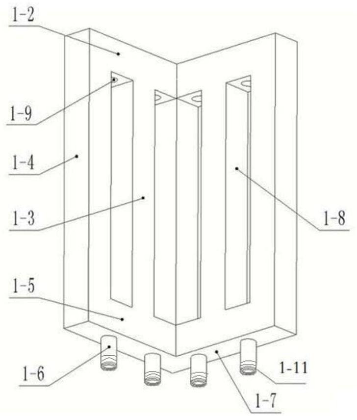
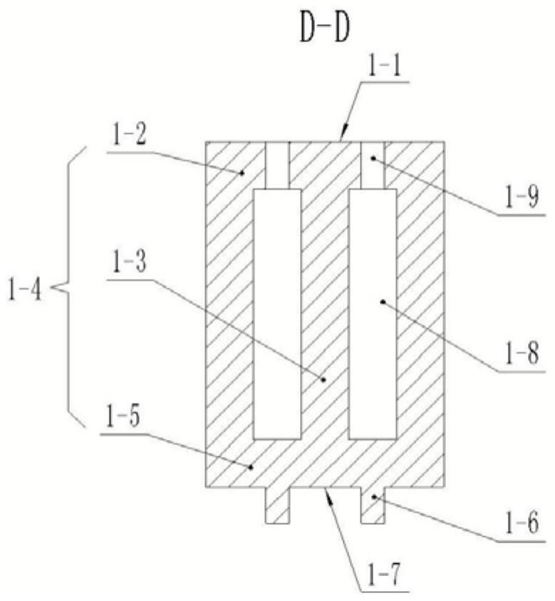
[0114] Such as Figure 1-4 Shown in , 6, and 13, the height of the superimposed frame stacker 1 is greater than the total height after the core tank is filled with rock cores, and the angle between the two support walls 1-4 is adapted to be 90° consistent with the rectangular angle of the core tank, The lower fitting surface 1-7 and the upper fitting surface 1-1 are horizontal fitting planes; the lower fitting surface 1-7 is provided with superimposed positioning pins...

Embodiment 2

[0128] as attached Figure 17 As shown, the receiver suitable for this embodiment is the framed object 4, the outer contour of the framed object 4 is circular, and each framed object 4 is provided with five resting lugs 2 evenly distributed along the circumferential direction. The top and bottom sides of the shelf code object 4 cannot be pushed against or pressed.

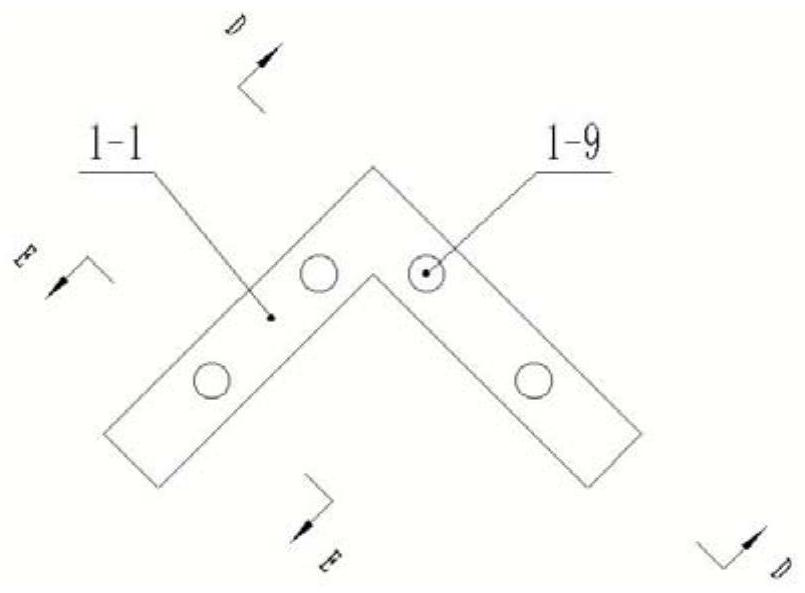
[0129] Such as Figure 1-4 As shown in , 17, the height of the superimposed racking device 1 is greater than the maximum height of the racking object 4, and the lower fitting surface 1-7 and the upper fitting surface 1-1 of the stacking racking device 1 are corner-shaped horizontal fittings Plane, the lower fitting surface 1-7 is respectively provided with two superimposed positioning pin holes 1-9 along the vertical and horizontal direction of the corner, and the upper fitting surface 1-1 is respectively provided with two overlapping positioning pins along the vertical and horizontal direction of the corner. Hol...

Embodiment 3

[0140] as attached Figure 25 As shown, the recipient applicable to this embodiment is a beam-shaped member 6 for constructing a frame-type structure, and the frame-type structure is a "Tian" shape with nine intersection points and four rectangular lattices arranged side by side. Grid layout, the combination requires multi-layer clip-hanging.

[0141] Such as Figure 5 As shown, the upper fitting surface 1-1 of the superimposed shelf coder 1 is provided with superimposed connecting concave tooth grooves, and the lower fitting surface 1-7 is provided with superimposed connecting convex teeth, and each supporting wall 1-4 is arranged on the upper wall beam 1 There are three rows of horizontal through holes 1-8 between -2 and the lower wall beam 1-5, each row of horizontal through holes 1-8 is two, and the included angle between the two supporting walls 1-4 is 90°.

[0142] Such as Figure 5 , 28 As shown in -30 and 32-34, the base 3 is a pier-shaped base 3, and the top surfa...


PUM


Abstract

The invention relates to the field of stacking and stacking devices for articles and the field of construction of frame structures, and aims to provide a multipurpose stacking frame stacker and a multipurpose stacking frame stacking combination device. The stacking racking device includes a corner-shaped wall structure connected by two supporting walls. The corner-shaped wall structure is provided with a vertical matching connection structure and a lateral matching connecting structure, so that the stacking racking device can pass through the vertical The mating connection structure and the mating connection structure of the racking object are sequentially stacked and connected vertically and / or laterally connected with the mating connection structure of the beam-shaped member through the lateral mating connection structure, or multiple stacking racks are passed through The vertical matching connection structures are stacked vertically in order to adjust the support height and / or the lateral matching connection structures are abutted to increase the number or thickness of the supporting walls. The beneficial effect of the invention is to facilitate layered stacking of various racking objects and rapid components of various frame structures.

Description

technical field [0001] The present invention relates to the field of stacking and stacking devices for articles and the field of construction of frame-type structures, in particular to a multi-purpose stacking frame stacker and a multi-purpose stacking frame stacking combination device. Background technique [0002] Since ancient times, there have been many items similar to the inventor's patent No. ZL201510144578.9, whose top and / or bottom surfaces cannot be compressed but require multi-layer stacks for centralized storage. For such items, the existing centralized storage technologies mainly include the following two types: [0003] One is to use packaging boxes to externally solidify and package such items and then stack them layer by layer. This method consumes a lot of man-hours, manpower, material resources, financial resources and three-dimensional space resources, and most of the packaging boxes are disposable applications. Therefore, it is neither economical nor env...

Claims


Application Information

Patent Timeline
Patent Type & Authority Patents(China)
IPC IPC(8): B65D6/08B65D6/16B65D21/032B65D21/028B65D25/22
CPCB65D7/14B65D7/24B65D9/12B65D11/14B65D11/18B65D21/0204B65D21/0209B65D25/22
Inventor 宋军
Owner 宋军
Why Eureka
Try Eureka