Inverter system with cooperative suppression of three-phase common-mode current and switching loss

A technology of switching loss and cooperative suppression, applied in the field of inverter system, can solve problems such as difficult direct use of three-level circuits, no consideration of influence, complex structure, etc., to improve inverter system efficiency, reduce switching loss, and simple structure clear effect

Active Publication Date: 2021-07-20
HEFEI UNIV OF TECH
View PDF3 Cites 0 Cited by
  • Summary
  • Abstract
  • Description
  • Claims
  • Application Information

AI Technical Summary

Problems solved by technology

[0005] 1) The lossless snubber circuit needs to be designed differently according to different switching frequencies and usage conditions, and the lossless snubber circuit uses many devices and has a complex structure;
[0006] 2) For the three-phase full-bridge two-level circuit, it is difficult for the inverter to be directly applied to the three-level circuit;
[0007] 3) The impact of the common-mode current generated by the parasitic capacitance of the inverter to the ground on the inverter performance is not considered
[0009] 1) When the inverter is fully loaded, the current is large, so that the differential common mode inductor gradually produces a saturation effect, resulting in a large current ripple, which affects the inverter performance, and the differential common mode inductor contains an air gap inside, which occupies a large space
[0010] 2) The inverter does not consider the high switching loss caused by high switching frequency;
[0011] 3) The inverter is designed for single-phase inverters, and its design is difficult to directly apply to three-phase inverters

Method used


Image

  • Inverter system with cooperative suppression of three-phase common-mode current and switching loss
  • Inverter system with cooperative suppression of three-phase common-mode current and switching loss
  • Inverter system with cooperative suppression of three-phase common-mode current and switching loss

Examples


Embodiment 1

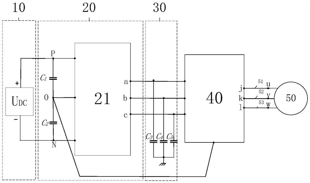
[0064] Embodiment 1: The three-phase common-mode current and switching loss cooperative suppression system of the present invention is simulated by means of a computer simulation tool. The filter circuit adopts the first circuit structure, and the DC voltage provided by the DC power supply system 10 is denoted as DC voltage U DC , in the normal operation of the inverter main circuit 21, the switch tube S ij The operating frequency is recorded as the switching frequency f s .

[0065] The parameter is set to DC voltage U DC is 300V, switching frequency f s at 40kHz, the sum of parasitic capacitances to ground and 1C ph1 is 2100pF, the sum of parasitic capacitance to ground is 2C ph2 is 10500pF, filter inductance L 1 , filter inductance L 2 , filter inductance L 3 90uH, filter capacitor C 6 , filter capacitor C 7 , filter capacitor C 8 is 10uF.

[0066] First set the current limiting capacitor C 3 , current limiting capacitor C 4 , current limiting capacitor C 5 i...


PUM


Abstract

The invention discloses an inverter system in which three-phase common-mode current and switching loss are suppressed cooperatively. The system includes a DC power supply system, a three-phase three-level ANPC inverter circuit, a three-phase current-limiting capacitor, a filter circuit, and a three-phase load. The DC power supply system provides DC voltage. The three-phase three-level ANPC inverter circuit includes an inverter main circuit and two identical support capacitors, and the three-phase current-limiting capacitor includes three identical current-limiting capacitors. The filter circuit includes two different circuit structures and is pulled back to the midpoint of the DC bus, and the three-phase load includes three AC buses. A three-phase common-mode current and switching loss cooperatively suppressed inverter system designed by the present invention uses a small number of auxiliary capacitors and inductances, occupies a small volume, and can cooperatively suppress the three-phase common-mode current and switching losses in a high switching frequency working environment. loss.

Description

technical field [0001] The invention relates to an inverter system for synergistic suppression of three-phase common-mode current and switching loss, belonging to the field of power electronic converters. Background technique [0002] Common-mode parasitic capacitance to ground is common in the inverter system, and the common-mode parasitic capacitance forms a common-mode loop with the ground, which easily generates common-mode current and affects the performance of the inverter. At the same time, in the inverter system, a higher switching frequency can improve the inverter efficiency but will significantly increase the switching loss. These two points are particularly serious in non-isolated photovoltaic inverters. Non-isolated photovoltaic inverters without transformers have attracted great attention due to their advantages of high efficiency and small size. However, due to the lack of transformer isolation, there is a common-mode loop between the photovoltaic system and ...

Claims


Application Information

Patent Timeline
Patent Type & Authority Patents(China)
IPC IPC(8): H02M7/483H02M1/12
CPCH02M1/126H02M7/483H02M1/0054H02M1/123Y02B70/10
Inventor 王佳宁梁成新胡嘉汶刘晓晖
Owner HEFEI UNIV OF TECH
Why Eureka
Try Eureka