Colored lamp device based on power line edge signal control

An edge signal, power line technology, applied to electrical components and other directions, can solve the problems of complex connection control circuits and high control costs, and achieve the effects of rich decorative effects, low cost, and simple circuit structure

Active Publication Date: 2020-01-24
HANGZHOU YUN LED CHIP PHOTOELECTRICITY TECH CO LTD
View PDF8 Cites 1 Cited by
  • Summary
  • Abstract
  • Description
  • Claims
  • Application Information

AI Technical Summary

Problems solved by technology

However, the control end of the controllable switch in the colored lamp device mentioned in the above patent is connected to the control circuit, the input end of the controllable switch is connect...

Method used


Image

  • Colored lamp device based on power line edge signal control
  • Colored lamp device based on power line edge signal control

Examples


Embodiment Construction

[0038] The present invention will be further described in detail with reference to the accompanying drawings and specific embodiments.

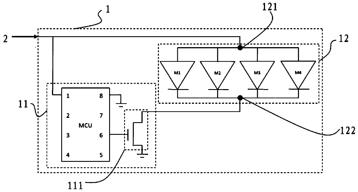
[0039] Such as figure 1 As shown, the color lamp device 1 based on the edge signal control of the power line provided by this embodiment includes:

[0040] The edge signal generator 11 is used to generate the edge signal and load the generated edge signal on the power line for output; the four LED modules 12 connected in parallel are respectively M1, M2, M3, M4, and the four LED modules 12 The anodes of the four LED modules are connected together to form the common anode 121 of the LED modules, and the cathodes of the four LED modules are connected together to form the common cathode 122 of the LED modules.

[0041] In this embodiment, a 5V DC power supply 2 is input.

[0042]The edge signal generator 11 of this embodiment includes a control circuit and a controllable switch module. The control circuit is composed of MCU. The port numbered...


PUM


Abstract

The invention provides a colored lamp device based on power line edge signal control. The colored lamp device comprises an edge signal generator and a plurality of LED modules. The edge signal generator is used for generating edge signals and loading the edge signals on a power line for output. Each LED module comprises an LED colored lamp set and an LED driver used for driving the LED colored lamp set according to the edge signals output by the power line. The LED modules are electrically connected to form an LED module common anode and an LED module common cathode. The edge signal generatorcomprises a controllable switch module and a control circuit. The controllable switch module comprises a switch module control end electrically connected with the control circuit, a switch module input end electrically connected with the LED module common cathode, and a switch module output end connected with a ground line. According to the colored lamp device, on-off of the power line is controlled by controlling on-off of the controllable switch module, then edge signals are output and loaded on the power line to drive the LED colored lamps and achieve different colored lamp effects, and thecircuit structure is simple.

Description

technical field [0001] The invention relates to the technical field of LED control, in particular to a colored lamp device controlled by an edge signal of a power line. Background technique [0002] At present, the LED lanterns on the market have a constant light mode and a flashing light mode. The constant light mode is easy to manufacture, but the decorative effect is monotonous. The main implementation methods of strings with flashing lights include: install LED flashing bulbs at intervals in the string of constant lights, but the lighting mode of this LED flashing bulbs is fixed, and it cannot receive control signals to achieve other changing effects: another way is to use LED colored lights Divided into several groups, each LED lantern is controlled by a separate controller. In order to achieve the effect of light string and flowing water, it must be made into a structure of more than 3 channels. The more channels, the better the effect. [0003] In the mode of dividi...

Claims


Application Information

Patent Timeline
IPC IPC(8): H05B45/30
CPCH05B45/30H05B45/20H05B47/185H05B45/46
Inventor 杨颖汉张梓珣
Owner HANGZHOU YUN LED CHIP PHOTOELECTRICITY TECH CO LTD
Why Eureka
Try Eureka