C-shaped steel stacking device

A technology of C-section steel and section steel, applied in the stacking, transportation and packaging of objects, conveyor objects, etc., can solve the problems of low degree of automation, low efficiency, waste of manpower, etc., and achieve the effect of reducing the amount of manual labor and hidden safety hazards.

Active Publication Date: 2021-04-02
浙江高圣钢结构有限公司
View PDF1 Cites 0 Cited by
  • Summary
  • Abstract
  • Description
  • Claims
  • Application Information

AI Technical Summary

Problems solved by technology

There are two common ways to place C-shaped steel: first, the openings of two C-shaped steels are opposite and staggered to form rectangular steel for stacking, see image 3 shown; in the second, the openings of the two C-shaped steels are relatively staggered, and part of the structure of one of the C-shaped steels is set in the third steel, see Figure 4 As shown, the stacking process of C-shaped steel commonly used in the prior art is: during the production process of C-shaped steel, after the C-shaped steel is discharged from the cold pressing device, it is directly transported to the stacking point by the hoisting equipment, and the C-shaped steel is manually stacked. Carry out reverse stacking, or use steel stacking machines for stacking, but the existing stacking methods, manual stacking is not only inefficient, but also wastes manpower, and the degree of automation is low. Machine stacking can only realize one of the two methods of C-shaped steel stacking The stacking scheme cannot be selected according to the actual situation

Method used


Image

  • C-shaped steel stacking device
  • C-shaped steel stacking device
  • C-shaped steel stacking device

Examples


Embodiment 1

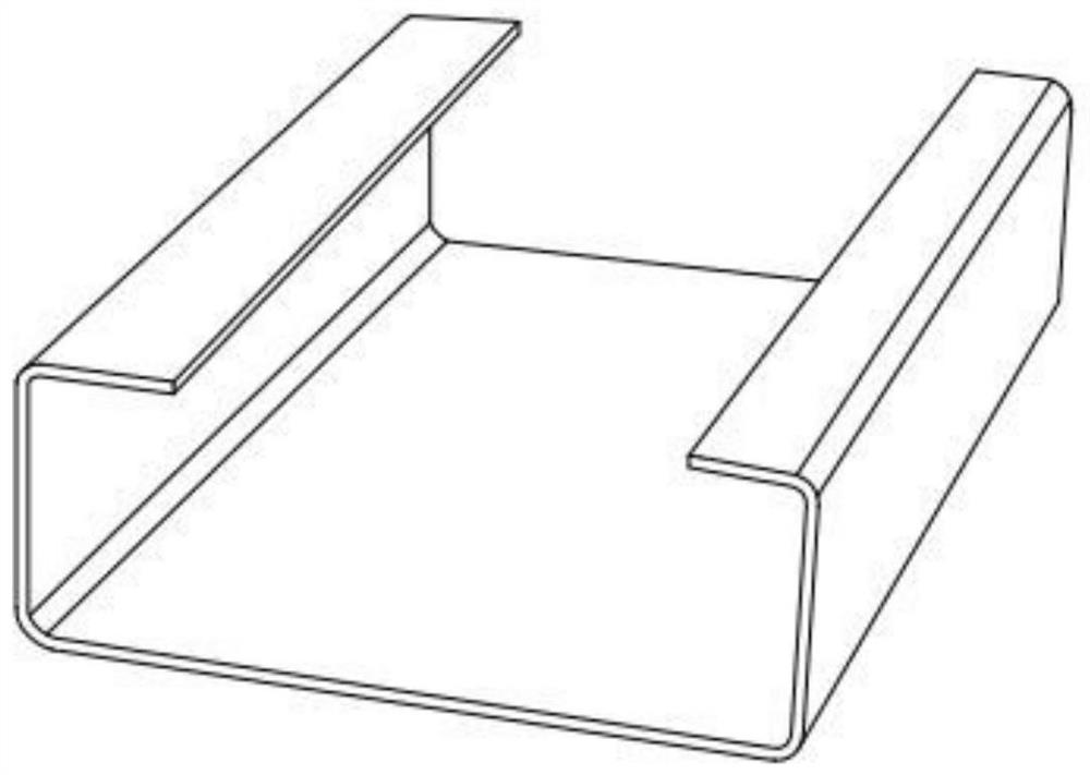
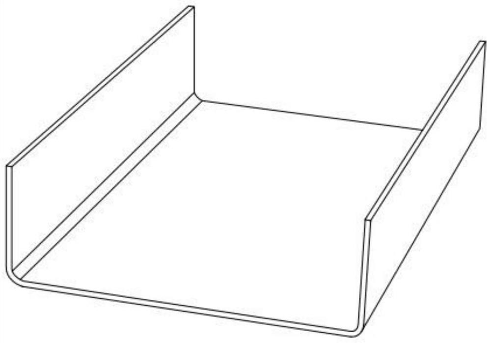
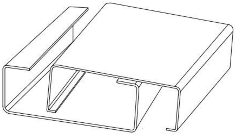
[0047] see Figure 5-14 As shown, the C-shaped steel stacking device includes:

[0048] The material receiving table 30 is arranged on one side of the shaped steel discharge port 100. The material receiving table 30 is provided with a first limit plate 31 for aligning the rectangular direction of the shaped steel. A moving assembly of a limiting plate 31,

[0049] The transfer assembly 50 is located on the corresponding side of the push assembly of the material receiving platform 30, and the transfer assembly 50 is used for section steel transfer,

[0050] The material receiving mechanism 60 is located in the discharge direction of the transmission assembly 50. The material receiving mechanism 60 includes a vertically arranged second frame body 62, and a hydraulic cylinder 65 for lifting the second frame body 62 is installed at the bottom of the second frame body 62. The sides corresponding to the two frames 62 and the conveying assembly 50 are respectively provided with a f...

Embodiment 2

[0073] When the C-shaped steel stacking device of the present invention is actually used:

[0074] Realize setting the device in the discharge direction of the C-shaped steel cutting discharge port 100 or the discharge direction of the discharge port 100 at the cold pressing device;

[0075] After the shaped steel is discharged from the discharge port, the discharged shaped steel is firstly received by the provided receiving table 30, and the first limiting plate 31 is used to limit the sliding distance of the discharged shaped steel, that is Alignment operation on section steel;

[0076] After finishing the profile alignment operation, the aligned profile steel is pushed towards the conveying assembly 50 using the pushing assembly arranged on one side of the material receiving table 30, and the process of conveying the profile steel on the conveying assembly 50 can effectively find defective profile steel and reject waste products, thereby Improve the stacking quality of sec...


PUM


Abstract

The invention discloses a C-shaped steel stacking device, and belongs to the technical field of steel stacking. The device comprises a material receiving table, wherein the material receiving table isarranged on one side of a discharge port of the shaped steel, and the material receiving table is provided with a first limiting plate used for aligning the length direction of the shaped steel; a pushing assembly is arranged on one side of the material receiving table, a conveying assembly is arranged on the corresponding side of the pushing assembly of the material receiving table, and a material receiving mechanism is arranged in the discharging direction of the conveying assembly; the material receiving mechanism comprises a second frame body, a hydraulic cylinder is mounted at the bottomof the second frame body, and the corresponding side surfaces of the second frame body and the conveying assembly are correspondingly provided with a first material receiving plate and a second material receiving plate; and the first material receiving plate is arranged above the second material receiving plate, a first driving motor is arranged on the second frame body, and the first driving motor is connected with the first material receiving plate. According to the device, the C-shaped steel is stacked through adopting mechanical equipment, manual work can be replaced, the shaped steel canbe aligned automatically in the stacking process, different stacking schemes can be selected according to the stacking requirements, the damage probability of the shaped steel in the stacking processdue to machine operation is low, the stacking effect is good, and the efficiency is high.

Description

technical field [0001] The invention belongs to the technical field of section steel stacking, and in particular relates to a C-section steel stacking device. Background technique [0002] C-shaped steel is a steel with a C-shaped cross section. For details, please refer to figure 1 , 2 As shown, C-shaped steel is mainly used in the construction field. There are two common ways to place C-shaped steel: first, the openings of two C-shaped steels are opposite and staggered to form rectangular steel for stacking, see image 3 shown; in the second, the openings of the two C-shaped steels are relatively staggered, and part of the structure of one of the C-shaped steels is set in the third steel, see Figure 4 As shown, the stacking process of C-shaped steel commonly used in the prior art is: during the production process of C-shaped steel, after the C-shaped steel is discharged from the cold pressing device, it is directly transported to the stacking point by the hoisting equi...

Claims


Application Information

Patent Timeline
Patent Type & Authority Patents(China)
IPC IPC(8): B65G47/22B65G47/82B65G57/11B65G57/081
CPCB65G47/22B65G47/82B65G57/081B65G57/11B65G2201/0214
Inventor 陈晓平盛长华
Owner 浙江高圣钢结构有限公司
Why Eureka
Try Eureka