Rear anti-collision beam energy absorption box and design method thereof

A rear anti-collision beam and energy-absorbing box technology, applied in computing, image data processing, 3D modeling, etc., can solve the problems of repairability of damage to the passenger compartment, impractical application of energy-absorbing boxes, and endangering the safety of drivers and passengers , to achieve the effect of low cost, light weight and simple manufacturing process

Active Publication Date: 2020-04-10
SHANGHAI TRACTOR & INTERNAL COMBUSTION ENGINE
View PDF12 Cites 2 Cited by
  • Summary
  • Abstract
  • Description
  • Claims
  • Application Information

AI Technical Summary

Problems solved by technology

The unsatisfactory energy absorption effect of the former leads to the force in the collision being easily transmitted to the frame structure, resulting in damage to the passenger compartment, poor maintainability and even endangering the safety of the passengers.
Although the latter can effectively improve the energy-absorbing capacity, due to its complicated process and high manufacturing cost, this type of energy-absorbing box has not been practically applied to the mass production of automobiles.

Method used


Image

  • Rear anti-collision beam energy absorption box and design method thereof
  • Rear anti-collision beam energy absorption box and design method thereof
  • Rear anti-collision beam energy absorption box and design method thereof

Examples


Embodiment Construction

[0038] The present invention will be further described below according to the accompanying drawings.

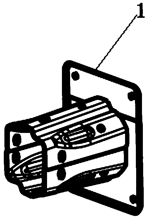
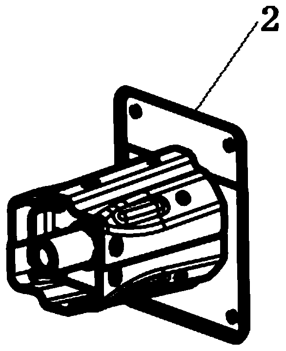
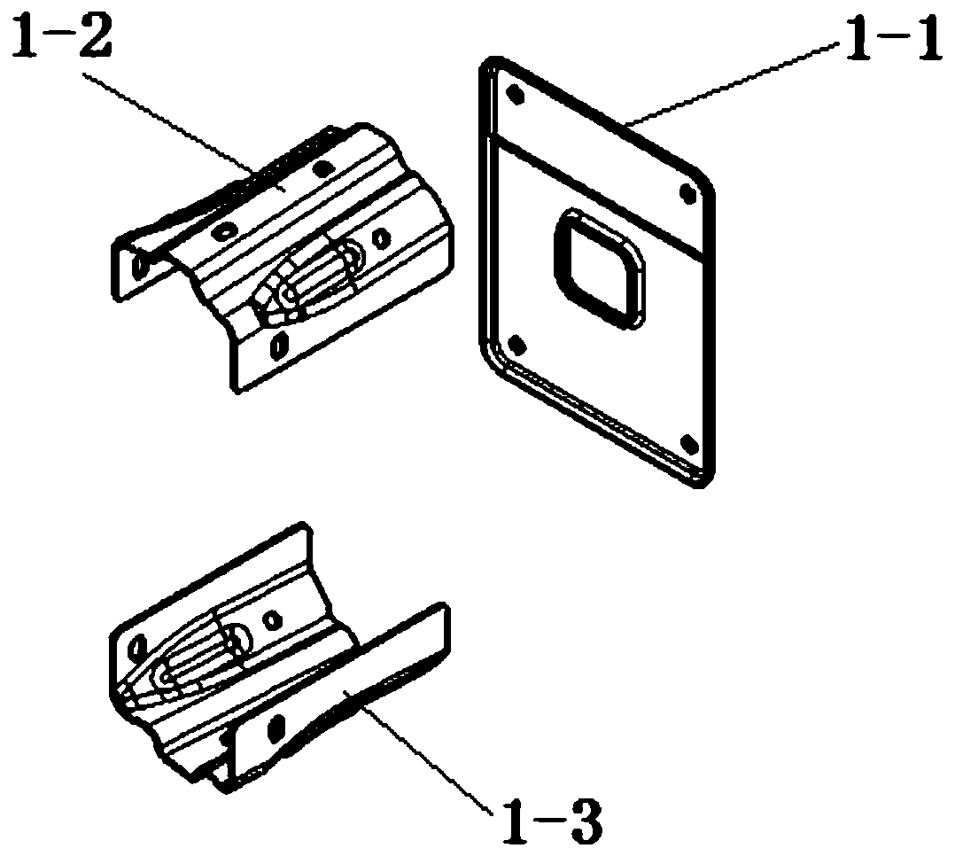
[0039] Such as Figure 1 to Figure 9 As shown, the rear sides of the left and right ends of the rear anti-collision beam are respectively connected to the left energy-absorbing box assembly 1 and the right energy-absorbing box assembly 2, and the left energy-absorbing box assembly 1 includes the left energy-absorbing box upper plate 1- 2. The lower plate 1-3 of the left energy-absorbing box and the sealing plate 1-1 of the left energy-absorbing box, the lower part of the upper plate 1-2 of the left energy-absorbing box is connected to the lower plate 1-3 of the left energy-absorbing box, which is located on the left energy-absorbing box The rear side of the plate 1-2 and the lower plate 1-3 of the left energy-absorbing box is connected to the left energy-absorbing box sealing plate 1-1; the right energy-absorbing box assembly 2 includes the right energy-absorbing box upper pl...


PUM


Abstract

The invention relates to the technical field of new energy vehicles, in particular to a rear anti-collision beam energy absorption box and a design method thereof. A rear anti-collision beam energy absorption box is characterized in that the rear sides of the left end and the right end of a rear anti-collision beam are connected with a left energy absorption box assembly and a right energy absorption box assembly respectively, the lower portion of a left energy absorption box upper plate is connected with a left energy absorption box lower plate, and the rear sides of the left energy absorption box upper plate and the left energy absorption box lower plate are connected with a left energy absorption box sealing plate; a right energy absorption box lower plate is connected to the lower portion of the right energy absorption box upper plate, a right energy absorption box sealing plate is connected to the rear sides of the right energy absorption box upper plate and the right energy absorption box lower plate, a tow hook reinforcing plate is embedded between the right energy absorption box upper plate and the right energy absorption box lower plate, and the middle of the tow hook reinforcing plate is connected with a tow hook threaded sleeve through threads. Compared with the prior art, the rear anti-collision beam energy absorption box and the design method thereof have the advantages that compared with a traditional anti-collision beam energy absorption box, the rear anti-collision beam energy absorption box is better in safety performance, light in weight, more stable in energy absorption, simple in production and manufacturing process, low in cost and wide in applicability.

Description

technical field [0001] The invention relates to the technical field of new energy vehicles, in particular to a rear anti-collision beam energy-absorbing box and a design method thereof. Background technique [0002] As cars enter thousands of households, consumers have higher and higher requirements for car safety performance. The crash box is an indispensable key component in the automobile anti-collision beam, and whether its function meets the requirements of safety performance is very important. At present, the energy-absorbing box of the anti-collision beam mostly adopts a structure with approximately equal cross-section or a multi-section structure composed of multiple parts. The unsatisfactory energy absorption effect of the former leads to the force in the collision being easily transmitted to the frame structure, resulting in damage to the passenger compartment, poor maintainability and even endangering the safety of the passengers. Although the latter can effecti...

Claims


Application Information

Patent Timeline
Patent Type & Authority Applications(China)
IPC IPC(8): G06F30/15G06T17/00
CPCG06T17/00
Inventor 郝大陆陈鲁王飞王思祖
Owner SHANGHAI TRACTOR & INTERNAL COMBUSTION ENGINE
Why Eureka
Try Eureka