Clamping device

A clamping device and clamping technology, applied in the mechanical field, can solve problems such as unreasonable structural design of the clamping device, and achieve the effect of good cooperative use, simple and reasonable structural design, and high safety

Inactive Publication Date: 2020-04-24
泰州市宏科电气配件有限公司
View PDF0 Cites 0 Cited by
  • Summary
  • Abstract
  • Description
  • Claims
  • Application Information

AI Technical Summary

Problems solved by technology

[0002] In the fixture, the device used to prevent the displacement or vibration of the workpiece during processing is called the clamping device. The existing clamping device has an unreasonable structural design and cannot meet the actual needs.

Method used


Image

  • Clamping device

Examples


Embodiment 1

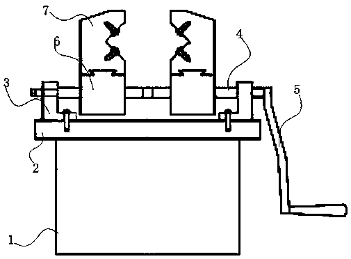
[0015] A clamping device, comprising a base 1, a clamping chassis 2, a screw base 3, a screw 4, a handle 5, a screw slider 6 and a V-shaped block 7; the clamping chassis 2 is fixed on the base 1, and the screw The rod base 3 is fixed on the clamping chassis 2, the lead screw slider 6 is movable on the lead screw 4, the lead screw 4 is set through the lead screw base 3, and one end of the lead screw 4 is fixedly connected with the handle 5; the lead screw slider 6 and V-shaped block 7 are fixedly connected; two screw sliders 6 are provided, and two V-shaped blocks 7 are provided.

Embodiment 2

[0017] The clamping chassis 2 of the clamping device of the present invention forms a detachable fixed connection with the base 1 through bolts, and the rest is consistent with the first embodiment.

Embodiment 3

[0019] The lead screw base 3 of the clamping device of the present invention is fixedly arranged on the clamping chassis 2 by welding, and the rest is consistent with Embodiment 1 or 2.


PUM


Abstract

The invention discloses a clamping device which comprises a base (1), a clamping base plate (2), a lead screw base (3), a lead screw (4), a handle (5), two lead screw sliding blocks (6) and two V-shaped blocks (7). The clamping base plate (2) is fixedly arranged on the base (1), the lead screw base (3) is fixedly arranged on the clamping base plate (2), the lead screw sliding blocks (6) are movably arranged on the lead screw (4), the lead screw (4) penetrates through the lead screw base (3), and one end of the lead screw (4) is fixedly connected with the handle (5); the lead screw sliding blocks (6) are fixedly connected with the V-shaped blocks (7); the two lead screw sliding blocks (6) are arranged, and the two V-shaped blocks (7) are arranged. The clamping device is simple and reasonable in structural design, capable of meeting the clamping requirement in existing workpiece production, good in cooperative use effect, capable of meeting the actual use requirement through mutual cooperation of all components and high in safety.

Description

technical field [0001] The invention relates to the mechanical field, in particular to a clamping device. Background technique [0002] In the fixture, the device used to prevent the displacement or vibration of the workpiece during processing is called a clamping device. The existing clamping device has an unreasonable structural design and cannot meet the actual needs. Contents of the invention [0003] The object of the present invention is to overcome the problems of the prior art and provide a clamping device. [0004] A clamping device of the present invention includes a base, a clamping chassis, a screw base, a screw, a handle, a screw slider and a V-shaped block; the clamping chassis is fixed on the base, and the screw base It is fixed on the clamping chassis, the screw slider is movable on the screw, the screw is set through the base of the screw, and one end of the screw is fixedly connected with the handle; the slider of the screw and the V The type blocks are...

Claims


Application Information

Patent Timeline
Patent Type & Authority Applications(China)
IPC IPC(8): B25B1/02B25B1/10
CPCB25B1/02B25B1/10
Inventor 圣明
Owner 泰州市宏科电气配件有限公司
Why Eureka
Try Eureka