Device for reducing operation vibration of steam turbine

A steam turbine and steam leakage technology, applied in the direction of machine/engine, mechanical equipment, engine components, etc., can solve the problems of large vibration of the mounting bearing of the seat cylinder, unbalanced heating of the cylinder, excessive negative expansion difference of the steam turbine, etc., to solve the axial displacement. and thermal expansion problems, avoid the thermal imbalance of the cylinder, and eliminate the effect of local thermal deformation

Pending Publication Date: 2020-05-12
中安联合煤化有限责任公司
View PDF0 Cites 0 Cited by
  • Summary
  • Abstract
  • Description
  • Claims
  • Application Information

AI Technical Summary

Problems solved by technology

The high water pressure acts on the condenser through the expansion joint of the circulating water pipe to generate an additional blind plate force, and then transmits it to the rear cylinder through the exhaust pipe, so that the contact stiffness between the rear cylinder and the seat plate is severely reduced, resulting in a The bearing installed on the cylinder vibrates greatly, which affects the normal operation of the steam turbine, and may cause damage to the steam turbine in severe cases
[0003] In addition, the steam leaked from the shaft seal at the high-pressure end of the steam turbine is mostly returned to the main body of the steam turbine through the circulation pipeline for recycling. However, since the steam leaked from the shaft seal at the high-pressure end is high-temperature steam, the heat will be conducted to the cylinder block of the steam turbine, resulting in the overall heating of the steam turbine. Uneven, which in turn leads to excessive negative expansion difference of the steam turbine and unbalanced local heating of the cylinder, which further leads to increased vibration of the bearing installed on the seat cylinder of the steam turbine, affecting the normal operation of the steam turbine

Method used


Image

  • Device for reducing operation vibration of steam turbine
  • Device for reducing operation vibration of steam turbine
  • Device for reducing operation vibration of steam turbine

Examples


Embodiment Construction

[0028] The following will clearly and completely describe the technical solutions in the embodiments of the present invention with reference to the accompanying drawings in the embodiments of the present invention. Obviously, the described embodiments are only some of the embodiments of the present invention, not all of them. Based on the embodiments of the present invention, all other embodiments obtained by persons of ordinary skill in the art without making creative efforts belong to the protection scope of the present invention.

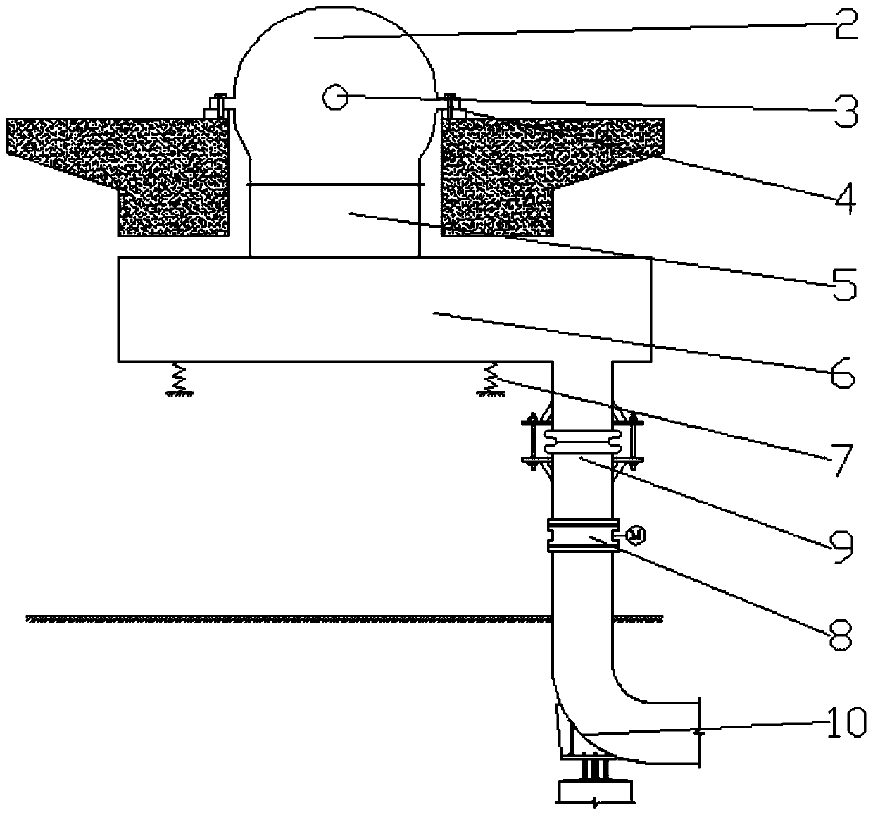
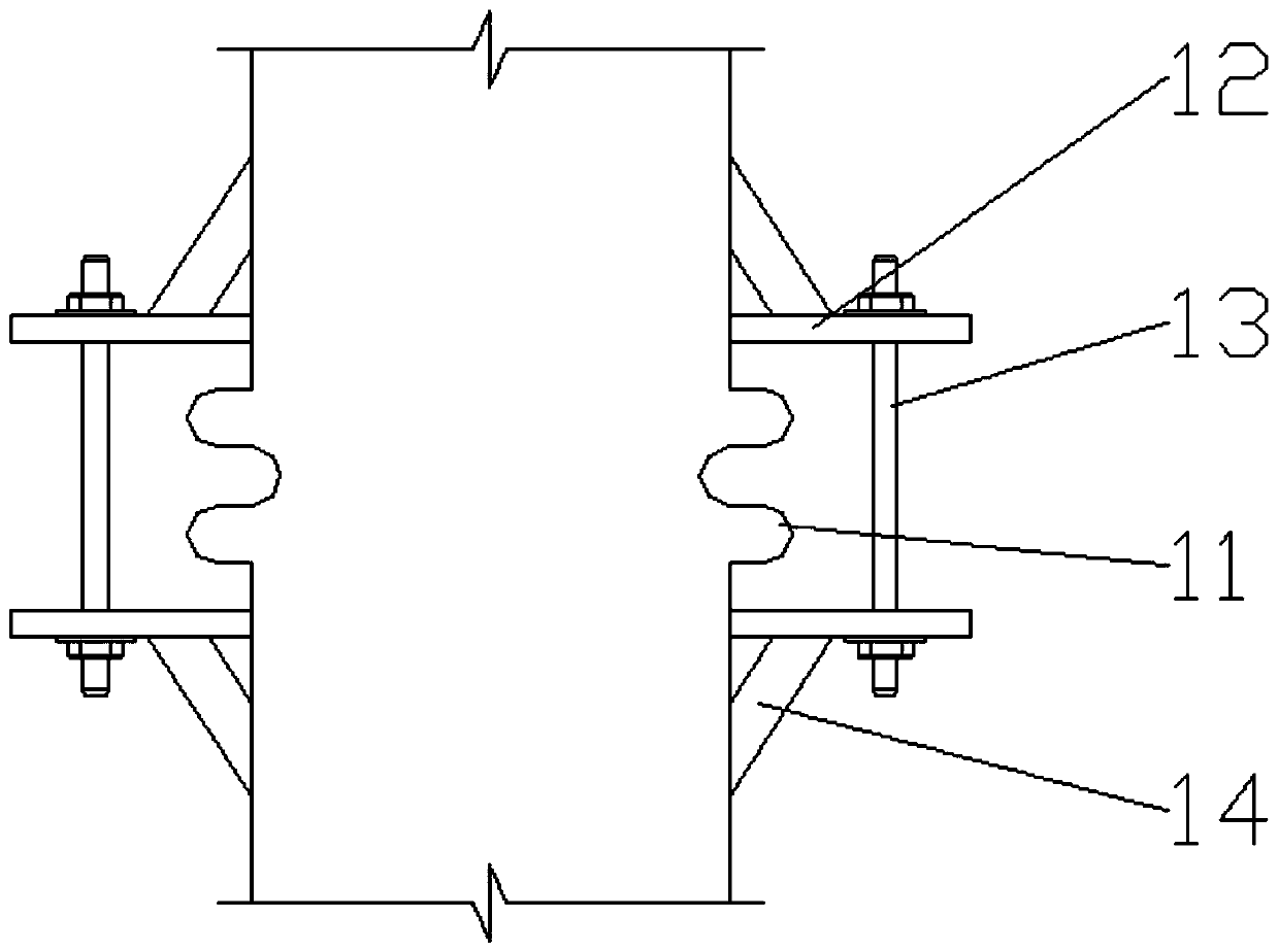
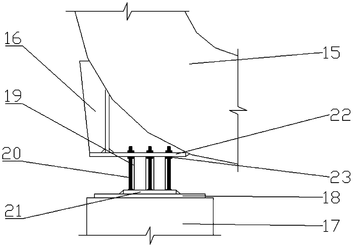
[0029] see Figure 1-5 , in an embodiment of the present invention, a device for reducing the operating vibration of a steam turbine includes a steam turbine body 1, the steam turbine body 1 includes a rear cylinder 2, and the rear cylinder 2 is fixedly connected to the support platform through the rear cylinder mounting plate 4, and the rear cylinder 2 includes the rear cylinder bearing 3 installed on the seat cylinder, the exhaust steam connect...


PUM


Abstract

The invention discloses a device for reducing the operation vibration of a steam turbine. The device comprises a steam turbine body; condenser spring support seats for supporting a condenser are arranged on the lower surface of the condenser; a circulating water pipe expansion part comprises an expansion joint connected onto a circulating water pipe; and an elbow joint part comprises a water pipeelbow and a support frame fixedly connected to the outer side of the water pipe elbow. Pull plates and pull rods are arranged at the expansion joint of the circulating water pipe of the steam turbine,water pipes at two ends of the expansion joint are fixedly connected together through the pull plates and the pull rods, and then the expansion joint is turned into a rigid whole; and when circulating water generates a blind plate force at the expansion joint, the extension of the circulation water pipe at the expansion joint is not caused, therefore, the problem of the rise of the condenser caused by the extension of the circulating water pipe can be avoided, and a thrust on a rear cylinder is not generated, so that the balanced stress on the cylinder is realized, the vibration generated dueto the stress imbalance is further avoided, and the operation stability of the steam turbine is ensured.

Description

technical field [0001] The invention relates to the technical field of steam turbines, in particular to a device for reducing the running vibration of a steam turbine. Background technique [0002] As a part of the self-provided power plant of the coal chemical enterprise, the steam turbine belongs to the public engineering system of the whole plant. The circulating water system of the condenser of the unit is subject to the circulating water system of the whole plant. The water pressure of the water system is 0.15-0.2MPa. The high water pressure acts on the condenser through the expansion joint of the circulating water pipe to generate an additional blind plate force, and then transmits it to the rear cylinder through the exhaust pipe, so that the contact stiffness between the rear cylinder and the seat plate is severely reduced, resulting in a The bearing installed on the cylinder vibrates greatly, which affects the normal operation of the steam turbine, and may cause dam...

Claims


Application Information

Patent Timeline
Patent Type & Authority Applications(China)
IPC IPC(8): F01D25/04F01D25/30F01D25/00
CPCF01D25/00F01D25/04F01D25/30
Inventor 刘振宇范志雄丁兆田丁书东刘杰陈件民
Owner 中安联合煤化有限责任公司
Why Eureka
Try Eureka