A rapid precipitation structure and precipitation method for confined water

A pressurized water and rapid technology, applied in the direction of infrastructure engineering, construction, etc., can solve the problems of engineering construction safety and construction progress, the inability to increase precipitation wells, and high cost of a single well, so as to improve construction flexibility and adjustability, reduce The effect of leaving underground obstacles and improving construction reliability

Active Publication Date: 2021-12-17
SHANGHAI GEOTECHN INVESTIGATIONS & DESIGN INST
View PDF5 Cites 0 Cited by
  • Summary
  • Abstract
  • Description
  • Claims
  • Application Information

AI Technical Summary

Problems solved by technology

The conventional confined water dewatering well structure has the following disadvantages: 1) A submersible pump needs to be installed in the well, the cost of a single well is high, and the area occupied is large, so the number of dewatering wells is limited. Once the dewatering well is blocked or the construction process The medium dewatering well is destroyed, and the dewatering well cannot be added after the excavation of the foundation pit in the later stage, which will have a great impact on the safety and construction progress of the project; 2) The depth of the confined water dewatering well is generally large, and submersible pumps are generally used However, once the submersible pump in the well fails, the pressurized water head may rise rapidly during the replacement of the submersible pump, resulting in the risk of inrush, which directly threatens the safety of the foundation pit; Hole, downhole pipe, welding, gravel throwing, clay ball throwing, well washing and other processes, the well completion time is long and the process is complicated; 4) The effect of sealing and water sealing needs to be improved; 5) The process of filter material filling and soil filling is complicated, and the construction efficiency lower

Method used


Image

  • A rapid precipitation structure and precipitation method for confined water

Examples


Embodiment Construction

[0032] The present invention will be further described below in conjunction with the accompanying drawings and specific embodiments.

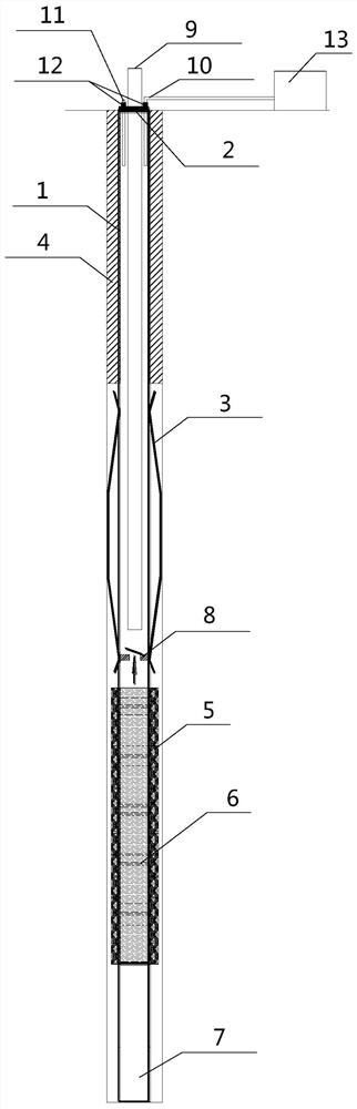
[0033] see figure 1 , this embodiment relates to a rapid dewatering well structure for pressurized water, which mainly includes a well pipe 1, a water-stop sealing section (the part of the sealing bag 3), a filter section (the part of the silk-wrapped filter 6), a sedimentation pipe section (the sedimentation pipe 7).

[0034] Well pipe 1, made of metal or plastic material, is connected to other parts of the well structure by welding or reliable mechanical connection;

[0035] Well pipe cover plate: the well pipe mouth is sealed at the ground end with a cover plate with openings to ensure air tightness; three openings are prefabricated on the well pipe cover plate 2, and the well pipe 1 is connected with a threaded seal;

[0036] Sealing section: the sealing bag 3 is made of high-strength tensile material. After being inserted into the well p...


PUM


Abstract

The invention relates to a rapid dewatering structure for pressurized water, which includes a well pipe, an air-filled pipe, and a water outlet pipe; a check valve is arranged in the well pipe, and the opening direction of the check valve is upward; and at least one seal is fixed outside the well pipe above the check valve The grouting pipe extends into the sealed bag; the water outlet pipe extends into the well pipe from top to bottom, and its lower end is above the check valve; one end of the inflation pipe extends into the well pipe, and the other end is connected to the pressure gas source. The present invention does not use a submersible pump, reduces the diameter of a single well, reduces the cost of a single well, improves the flexibility and adjustability of construction, improves the construction reliability, and simplifies the construction process; forms a high-strength sealed water-stop structure; adopts a filter section with a water-permeable structure outsourced The structure type can be prefabricated on the ground. After the hole is formed, the well structure is directly lowered and the well construction is completed after grouting and sealing. There is no need to fill filter materials, clay balls and other processes. Rainwater wells are economical to build and energy efficient to operate.

Description

technical field [0001] The invention relates to a rapid dewatering structure for pressurized water, which belongs to the technical field of dewatering wells for pressurized water. Background technique [0002] With the continuous development of my country's urbanization process, the development scope of underground space has been continuously expanded, and the depth of foundation pits has also increased. The effective dewatering of the foundation pit is a prerequisite to ensure the safety of the foundation pit construction and the construction period. For the confined water precipitation, during the construction process, it is necessary not only to prevent inrush in the pit due to insufficient precipitation, but also to avoid soil settlement caused by excessive precipitation. [0003] At present, conventional confined water dewatering wells generally use submersible pumps to pump water into the well, so the diameter of the well usually needs to be greater than 200mm, the di...

Claims


Application Information

Patent Timeline
Patent Type & Authority Patents(China)
IPC IPC(8): E02D19/10E02D19/16
CPCE02D19/10E02D19/16E02D2250/003
Inventor 顾国荣杨石飞路家峰梁振宁罗志华姜宇张晗陈海洋
Owner SHANGHAI GEOTECHN INVESTIGATIONS & DESIGN INST
Why Eureka
Try Eureka