Micro-LED display device, display panel and manufacturing method thereof

A display panel and manufacturing method technology, applied in the direction of instruments, electrical components, electric solid devices, etc., can solve the problems of reduced binding accuracy, small size of Micro-LED chips, errors, etc., to improve the binding accuracy and reduce the arrangement effect of error

Inactive Publication Date: 2020-07-28
XIAMEN QIANZHAO SEMICON TECH CO LTD
View PDF21 Cites 0 Cited by
  • Summary
  • Abstract
  • Description
  • Claims
  • Application Information

AI Technical Summary

Problems solved by technology

[0004] However, due to the extremely small size of the Micro-LED chip, the number of Micro-LED chips that need to be bonded on the substrate of the display device is huge, so errors will be brought about during the bonding process, resulting in a decrease in the bonding accuracy

Method used


Image

  • Micro-LED display device, display panel and manufacturing method thereof
  • Micro-LED display device, display panel and manufacturing method thereof
  • Micro-LED display device, display panel and manufacturing method thereof

Examples


Embodiment Construction

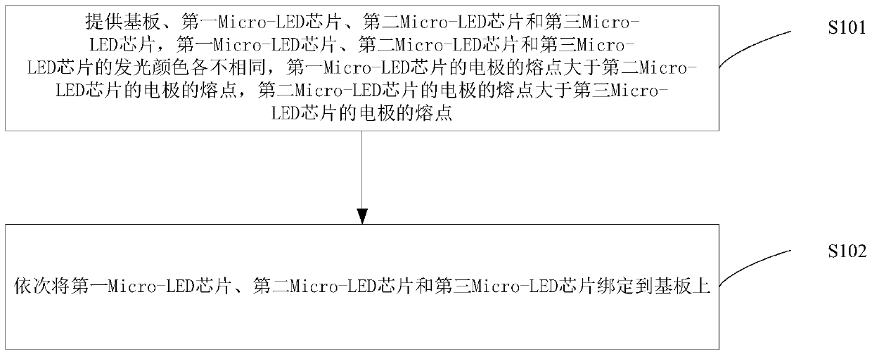
[0038] As mentioned in the background art, the binding accuracy of Micro-LED chips in existing Micro-LED display devices is low. The inventor found that the main reason for this problem is that the metal electrode materials of all Micro-LED chips are the same, so the melting points of the metal electrodes of all Micro-LED chips are the same. The Micro-LED chip is bound to the substrate of the display device in batches. During the subsequent chip binding process, the metal electrodes of the previously bound chip will be heated and dissolved, causing the position of the chip to shift.

[0039] Based on this, in the prior art, only the method of arranging the Micro-LED chips on the temporary substrate in stages, and then using the temporary substrate to transfer all the Micro-LED chips to the substrate of the display device for binding, however, When binding in this way, in the process of arranging the Micro-LED chips according to the colors, there will be errors in the arrangeme...


PUM

PropertyMeasurementUnit
melting pointaaaaaaaaaa

Abstract

The invention provides an Micro-LED display device, a display panel and a manufacturing method thereof. The melting point of a first Micro-LED chip electrode is greater than the melting point of a second Micro-LED chip electrode, the melting point of a second Micro-LED chip electrode is greater than that of a third Micro-LED chip electrode, therefore, a first Micro-LED chip, a second Micro-LED chip and a third Micro-LED chip can be bound to a substrate in sequence, and the first Micro-LED chip, the second Micro-LED chip and the third Micro-LED chip do not need to be arranged to a temporary substrate by several times and then transferred to the substrate of the display panel at the same time, so that the arrangement error is reduced and the binding precision is improved.

Description

technical field [0001] The present invention relates to the technical field of Micro-LED display, and more specifically, to a Micro-LED display device, a display panel and a manufacturing method thereof. Background technique [0002] Because Micro-LED display devices have the advantages of high efficiency, high brightness, high reliability, energy saving, small size and small thickness, Micro-LED display devices have become a new generation of widely used display devices. [0003] In the production process of Micro-LED display equipment, it is necessary to make Micro-LED chips one by one, and then arrange the Micro-LED chips of red, green and blue three times on a temporary substrate, and then use the arrangement A good temporary substrate transfers and binds the Micro-LED chip to the substrate of the display device to realize the full color of the display device. [0004] However, due to the extremely small size of the Micro-LED chip, the number of Micro-LED chips that nee...

Claims


Application Information

Patent Timeline
Patent Type & Authority Applications(China)
IPC IPC(8): G09F9/33H01L27/15
CPCG09F9/33H01L27/156
Inventor 艾国齐谈江乔柯志杰柯毅东段方方
Owner XIAMEN QIANZHAO SEMICON TECH CO LTD
Why Eureka
Try Eureka