
Planting device capable of punching holes simultaneously based on landscape gardens
A planting device and gardening technology, applied in planting methods, horticulture, forestry, etc., can solve the problems of transplanting soil, the inability to control the soil depth of transplanted seedlings, and the inability to open holes for transplanting at the same time, so as to reduce manpower and be convenient and fast human effect
- Summary
- Abstract
- Description
- Claims
- Application Information
AI Technical Summary
Problems solved by technology
Method used
Image

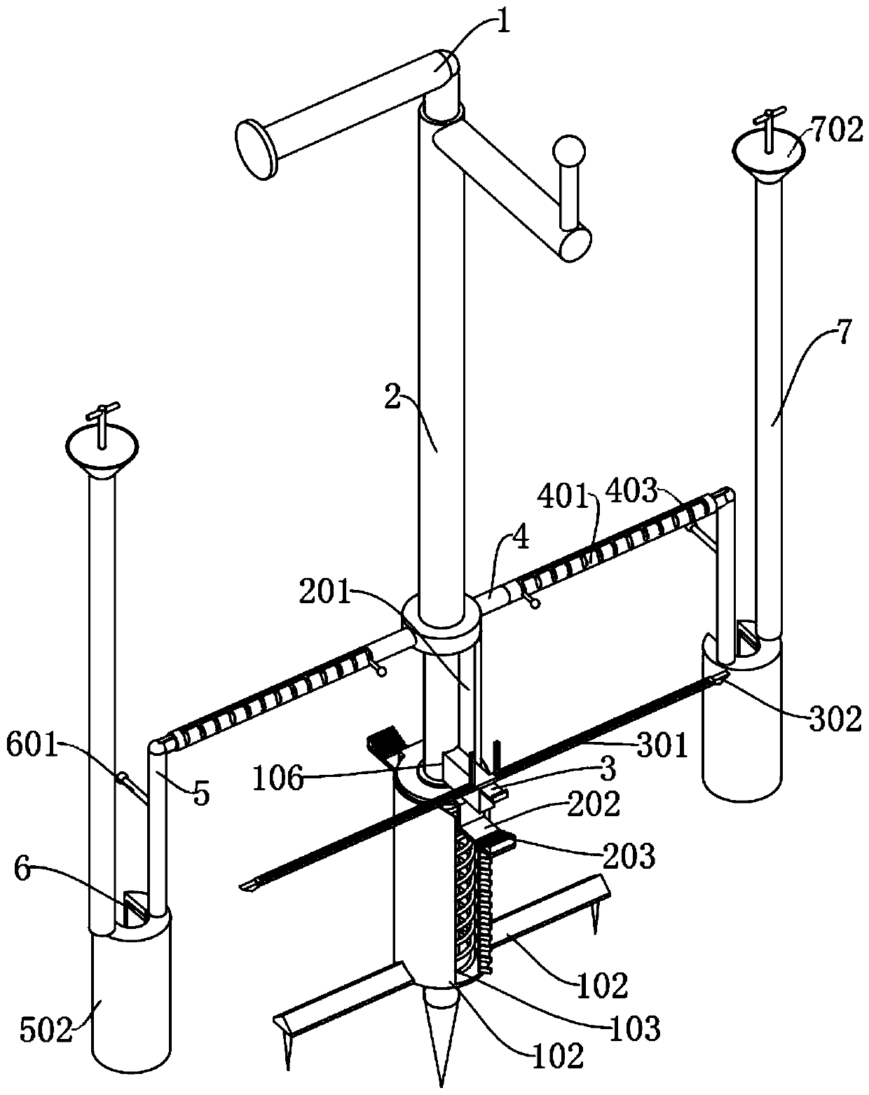
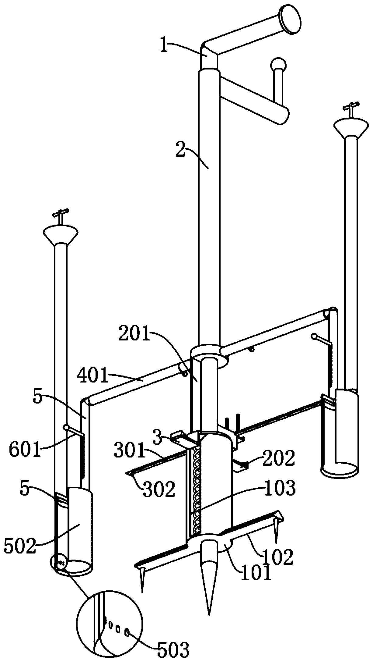
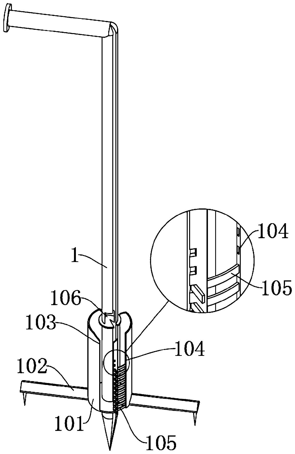
Examples
Embodiment
[0035] as attached figure 1 to attach Figure 9 Shown:
[0036] The present invention provides a planting device that can simultaneously open holes based on landscape gardens, including: a main body 1, a moving part 2, a limit block 3, a side rod 4, an adjustment rod 5, a top plate 6 and a side bin 7; the main body 1 is L-shaped structure, and the cross-section of the main body 1 is a cylindrical structure, and the bottom of the main body 1 is a conical structure; the middle position of the main body 1 is provided with a limit plate with a cylindrical plate structure; the front end of the limit block 3 is provided with a L shaped structure of the puller, and the rear end of the limit block 3 is embedded in the installation groove 106; the inner end of the side bar 4 is connected to both sides of the bottom of the moving part 2; And the outside of the adjustment head 501 at the inner end of the top end of the adjustment rod 5 is provided with an operating rod, and the operati...
PUM
 Abstract
Description
Claims
Application Information