A kind of annular oxygen supply equipment for aquaculture pond

An aquaculture and oxygen supply technology, applied in the application, fish farming, animal husbandry and other directions, can solve the problems of turbid water quality, affecting fish farming, etc., achieve the effect of clear water quality, reduce the probability of contact, and prevent the feces from being washed away

Active Publication Date: 2021-09-07
佛山市嘉沃农业科技合伙企业(有限合伙)
View PDF4 Cites 0 Cited by
  • Summary
  • Abstract
  • Description
  • Claims
  • Application Information

AI Technical Summary

Problems solved by technology

[0003] Since the oxygen supply equipment is at the bottom of the pool for oxygen supply, the oxygen will be sent directly from the bottom, and the feces produced by the fish will sink to the bottom of the pool under the influence of gravity, and will contact the oxygen sent vertically during this process, making the feces Dissipated by oxygen, which in turn causes the water quality in the breeding pond to become turbid, affecting fish farming

Method used


Image

  • A kind of annular oxygen supply equipment for aquaculture pond
  • A kind of annular oxygen supply equipment for aquaculture pond
  • A kind of annular oxygen supply equipment for aquaculture pond

Examples


Embodiment 1

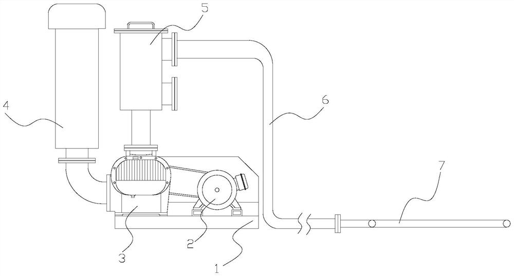
[0028] Example 1: Please refer to Figure 1-Figure 4 , the specific embodiments of the present invention are as follows:

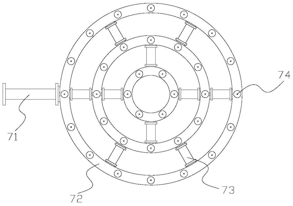
[0029] Its structure includes a base 1, a motor 2, a blower 3, an air intake pipe 4, a filter barrel 5, an air supply pipe 6, and an oxygen supply structure 7. The motor 2 is horizontally installed on the upper end of the base 1 and is mechanically connected. The blower 3 is fixed on The upper end of the base 1 is connected with the motor 2 through a belt, the air intake pipe 4 is installed on the left end of the blower 3 and fixed by bolts, the filter barrel 5 is vertically installed on the front end of the blower 3 and is mechanically connected, and the air supply pipe 6 is fixed The upper end on the right side of the filter barrel 5 is connected to the inner side, and the oxygen supply structure 7 is horizontally installed on the right end of the air supply pipe 6; the oxygen supply structure 7 includes a connecting pipe 71, an annular pipe 72, a branch...

Embodiment 2

[0034] Example 2: Please refer to Figure 4-Figure 8 , the specific embodiments of the present invention are as follows:

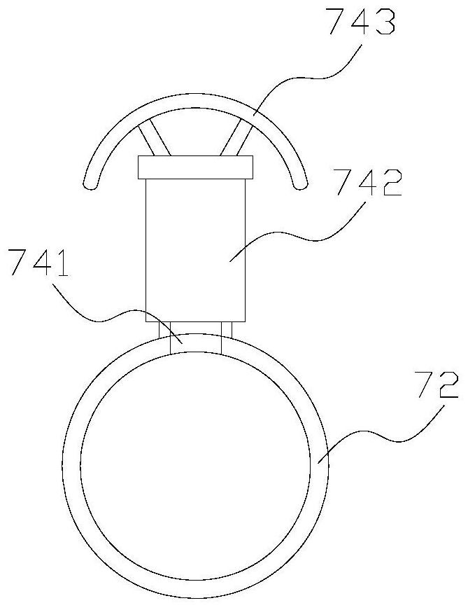
[0035]The ejection structure 742 includes a pipe body 42a, an ejection port 42b, a spring 42c, a movable structure 42d, an air inlet 42e, and a limiting structure 42f. The ejection port 42b runs through the outside of the pipe body 42a, and the spring 42c is embedded and installed On the inner side of the tube body 42a and against the upper end of the movable structure 42d, the movable structure 42d is embedded in the inner side of the tube body 42a and adopts a flexible connection, and the limiting structure 42f is fixed on the inner bottom of the tube body 42a and is arranged below the movable structure 42d, The air inlet 42e passes through the tube body 42a and the limiting structure 42f.

[0036] refer to Figure 5 The movable structure 42d includes a rolling frame d1, a driving frame d2, a turret d3, a ball d4, and an oxygen supply chamber d5. The r...


PUM


Abstract

The invention discloses a ring-shaped oxygen supply device for aquaculture ponds. The structure includes a base, a motor, a blower, an air intake pipe, a filter bucket, an air supply pipe, and an oxygen supply structure. The motor is horizontally installed on the upper end of the base, and the blower is fixed on the upper end of the base. The air inlet pipe is installed on the left end of the blower, the filter barrel is installed vertically on the front end of the blower, the air supply pipe is fixed on the upper right side of the filter barrel, and the oxygen supply structure is installed horizontally on the right end of the air supply pipe. structure, the connecting pipe is fixed on the left side of the annular pipe, and the present invention sets an output structure on the upper end of the annular pipe to make it spread out horizontally, reducing the contact probability with fish feces, thereby ensuring the clarity of the water quality; in the movable structure The lower end is equipped with a limit structure to send out oxygen intermittently, making it less likely to contact the sinking feces, thereby preventing the feces from being washed away, ensuring the inventory of water quality, and better breeding of fish.

Description

technical field [0001] The invention belongs to the field of aquaculture, and in particular relates to an annular oxygen supply device for aquaculture ponds. Background technique [0002] Aquaculture is mainly the cultivation of aquatic animals and plants, including fish cultivation, and fish cultivation includes natural cultivation and artificial cultivation. In artificial cultivation, batch cultivation is usually carried out in specific aquaculture ponds. In order to ensure the normal breeding life of fish, it is necessary to supply oxygen in the culture pond to ensure that more fish can be carried in the pond, but the prior art has the following deficiencies: [0003] Since the oxygen supply equipment is at the bottom of the pool for oxygen supply, the oxygen will be sent directly from the bottom, and the feces produced by the fish will sink to the bottom of the pool under the influence of gravity, and will contact the oxygen sent vertically during this process, making th...

Claims


Application Information

Patent Timeline
Patent Type & Authority Patents(China)
IPC IPC(8): A01K63/04
CPCA01K63/042
Inventor 陈丽清
Owner 佛山市嘉沃农业科技合伙企业(有限合伙)
Why Eureka
Try Eureka