Plasma waste gas treatment equipment

A technology for waste gas treatment equipment and plasma, applied in gas treatment, lighting and heating equipment, separation methods, etc., can solve the problems of slow waste gas filtration, unfavorable use, poor filtration quality, etc., to achieve the effect of strengthening filtration, strong wind power, wide area effect

Pending Publication Date: 2020-11-03
江苏众明环保科技有限公司
View PDF0 Cites 0 Cited by
  • Summary
  • Abstract
  • Description
  • Claims
  • Application Information

AI Technical Summary

Problems solved by technology

[0005] The present invention aims to solve the problem that the existing plasma waste gas treatment equipment has a single structure design, the wind force inside the box is small when the waste gas is filtered, the process of filtering the waste gas is slow, and the quality of the filter is poor. During the process, the dust-proof effect inside the device is poor, and the dust in the exhaust gas is easy to accumulate inside the device, resulting in damage to the device, which is not conducive to actual use. A plasma waste gas treatment equipment is provided. By setting a fixed block, a fan, a spray gun, The dust collection panel and the vacuum cleaner make the structure of the device stable, and the wind force inside the device is increased through the fan, the process of filtering the exhaust gas is faster, and the filtering effect is strengthened, and the vacuum cleaner installed inside the device can absorb the dust into the dust collection box , to prevent a large amount of dust and impurities in the exhaust gas from floating around with the exhaust gas during the process of filtering the exhaust gas, causing dust to accumulate inside the device, which in turn leads to the problem that the device is easily damaged

Method used


Image

  • Plasma waste gas treatment equipment
  • Plasma waste gas treatment equipment
  • Plasma waste gas treatment equipment

Examples


Embodiment

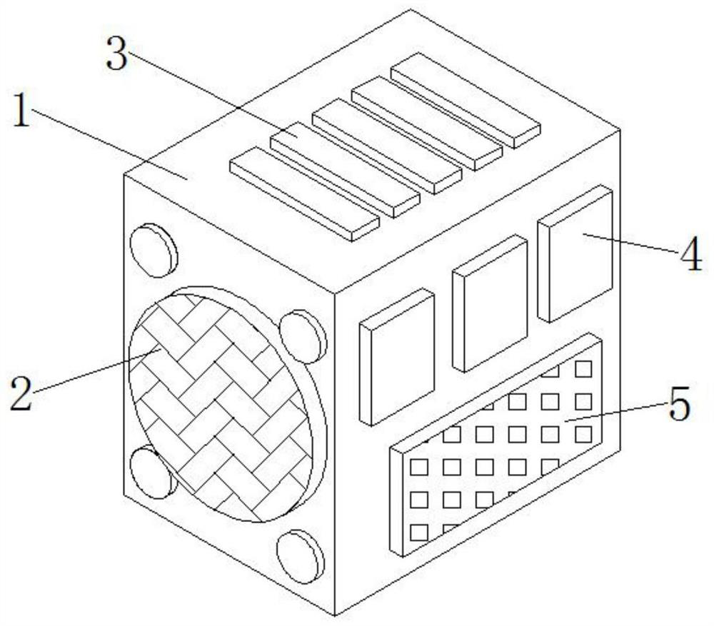
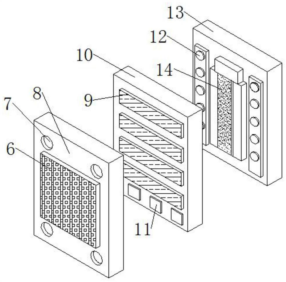
[0025] refer to Figure 1-4 ,

[0026] A plasma exhaust gas treatment device provided in this embodiment includes a chassis 1, an air outlet 2 and a cooling outlet 3, the air outlet 2 is located on the left side outside the chassis 1, and the air outlet 2 is movably connected to the chassis 1, and the top of the chassis 1 is provided with a heat dissipation port 3, and the heat dissipation port 3 is fixedly connected to the chassis 1, the upper right side outside the chassis 1 is provided with a wire storage box 4, and the wire storage box 4 is fixedly connected to the chassis 1, and the lower right side outside the chassis 1 is provided with a control box 5, and The control box 5 is fixedly connected with the cabinet 1, the inside of the cabinet 1 is provided with a filter panel 8, and the filter panel 8 is movably connected with the cabinet 1, and the left side of the filter panel 8 is provided with a primary filter 6, and the primary filter 6 is fixedly connected with the ...


PUM


Abstract

The invention provides plasma waste gas treatment equipment, which belongs to the technical field of waste gas treatment, and comprises a case, an air outlet and a heat dissipation opening, the air outlet is located at the left side outside the case and is movably connected with the case, the heat dissipation opening is formed in the top of the case and is fixedly connected with the case, and a wire storage box is arranged at the upper end of the right side outside the case; a control box is arranged at the lower end of the right side of the exterior of the case, and the control box is fixedlyconnected with the case. The plasma waste gas treatment equipment is stable in structure, when the plasma waste gas treatment equipment is actually used, wind power in the plasma waste gas treatmentequipment is increased through the fan, the waste gas filtering process is rapid, the filtering effect is enhanced, and the dust collector arranged in the plasma waste gas treatment equipment can suckdust into the dust collecting box; therefore, the problem that in the waste gas filtering process, a large number of dust impurities in waste gas drift away along with the waste gas, dust is accumulated in the device, and then the device is prone to damage is solved.

Description

technical field [0001] The invention relates to the technical field of waste gas treatment, in particular to plasma waste gas treatment equipment. Background technique [0002] Exhaust gas treatment equipment mainly refers to a kind of environmental protection equipment that protects the environment and purifies the air by recycling or removing and reducing harmful components of exhaust gas by using different technologies, so that our environment will not be polluted. [0003] However, the existing plasma waste gas treatment equipment has a single structure. When the waste gas is filtered, the wind force inside the box is small, the process of filtering the waste gas is slow, and the quality of the filter is poor. The dust-proof effect inside the device is poor, and the dust in the exhaust gas is easy to accumulate inside the device, resulting in damage to the device, which is not conducive to actual use. [0004] Therefore, it is necessary to upgrade and transform the exis...

Claims


Application Information

Patent Timeline
Patent Type & Authority Applications(China)
IPC IPC(8): B01D53/32B01D46/00B01D46/12B01D50/00F24F6/12F24F5/00F24F13/00
CPCB01D46/0041B01D46/12B01D50/00B01D53/32B01D2258/02B01D2259/818F24F5/0007F24F6/12F24F13/00Y02B30/54
Inventor 杜鹏飞
Owner 江苏众明环保科技有限公司
Why Eureka
Try Eureka