Automatic welding device for brake iron shoe

A technology of automatic welding and iron hoof, which is applied in the direction of auxiliary devices, welding equipment, auxiliary welding equipment, etc., to achieve the effects of ensuring health, convenient and fast clamping, and avoiding conflicts

Active Publication Date: 2020-12-15
浙江德清精艺汽配有限公司
View PDF10 Cites 0 Cited by
  • Summary
  • Abstract
  • Description
  • Claims
  • Application Information

AI Technical Summary

Problems solved by technology

[0004]Aiming at the deficiencies of the prior art, the present invention provides an automatic brake shoe welding device, which is equipped with a clamping device that is easy to adjust and can weld workpieces of various sizes and other advantages, it solves the problem that the welding device can only process and weld workpieces of a single size

Method used


Image

  • Automatic welding device for brake iron shoe
  • Automatic welding device for brake iron shoe
  • Automatic welding device for brake iron shoe

Examples


Embodiment Construction

[0029] The following will clearly and completely describe the technical solutions in the embodiments of the present invention with reference to the accompanying drawings in the embodiments of the present invention. Obviously, the described embodiments are only some, not all, embodiments of the present invention. Based on the embodiments of the present invention, all other embodiments obtained by persons of ordinary skill in the art without making creative efforts belong to the protection scope of the present invention.

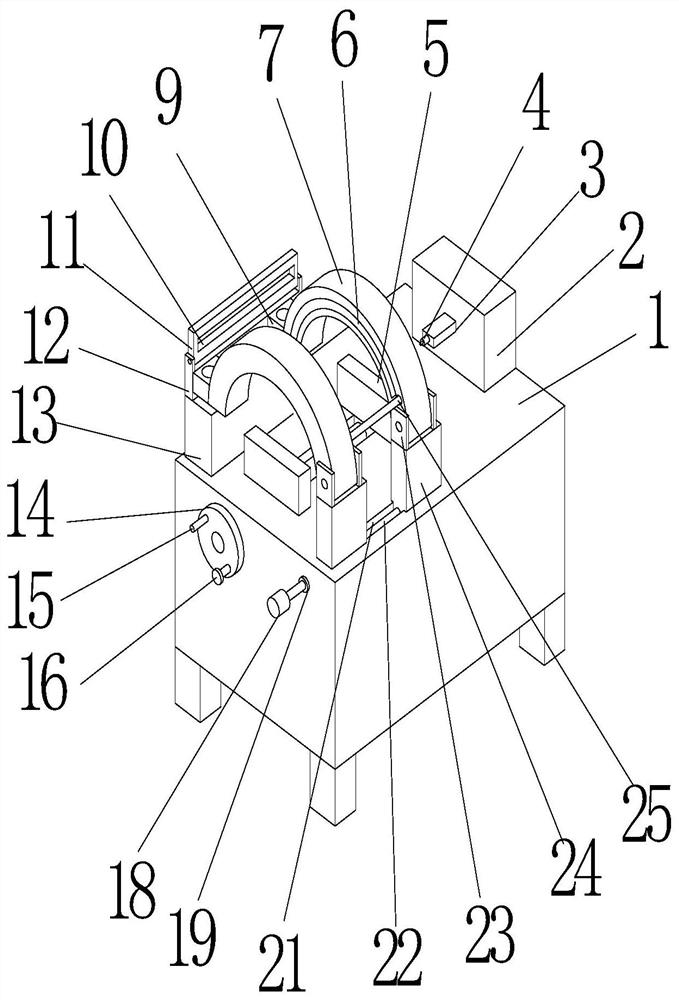
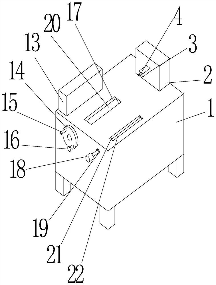
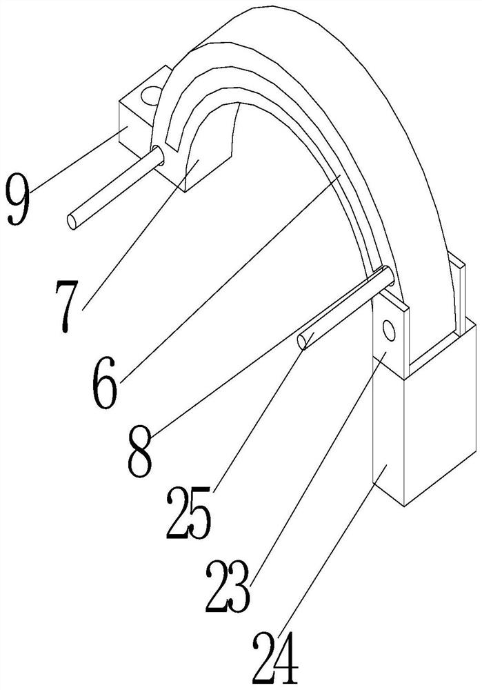
[0030] see Figure 1-Figure 6 , the present invention provides a technical solution: a brake shoe automatic welding device, including a workbench 1, the top of the workbench 1 is fixedly connected with a control box 2, the control box 2 is an existing structure, and will not be repeated here. The control box 2 is connected to an external power supply to start. The left side of the control box 2 is provided with a telescopic rod 3. The telescopic rod 3 is an ex...


PUM


Abstract

The invention relates to the technical field of welding devices, and discloses an automatic welding device for a brake iron shoe. The automatic welding device comprises a workbench, wherein the top ofthe workbench is fixedly connected with a control box; the left side of the control box is equipped with a telescopic pole; the left side of the telescopic pole is fixedly connected with a welding head; a movable slot I is formed in the top of the workbench; and the top of the workbench is equipped with a fixed clamping device. A workpiece is put between two clamping plates I, a half-moon-shapedworkpiece is clamped into a clamping slot, and a rotary column rotates, so that a threaded rod I rotates, and therefore, two fixed blocks I relatively move on the surface of the threaded rod I; and the two fixed blocks I relatively move to drive the two clamping plates I to clamp the workpiece, so that a half-moon-shaped clamping device can clamp half-moon-shaped workpieces of different dimensions, and therefore, workers clamp the half-moon-shaped workpieces more conveniently and quickly to a certain extent.

Description

technical field [0001] The invention relates to the technical field of welding devices, in particular to an automatic welding device for brake shoes. Background technique [0002] At present, the brake iron ride is also called the brake iron shoe. The brake iron shoe refers to the accessories that are pushed outward by the action of the brake cam or the push rod to suppress the brake drum to exert the braking effect. It is installed on the brake drum and is a part of the automobile braking system. One of the key safety parts, the shape of the brake shoe is like a half-moon. When the brakes are applied, the two half-moon-shaped brake shoes are stretched out under the action of the brake wheel cylinder, and the brake shoes are propped up to rub against the inner wall of the brake drum to slow down. Or the effect of parking, in the production process, the reinforcement and the panel need to be spot-welded; but the current welding device is composed of a welding device and a cla...

Claims


Application Information

Patent Timeline
Patent Type & Authority Applications(China)
IPC IPC(8): B23K37/04B23K37/02B23K37/00
CPCB23K37/0435B23K37/0252B23K37/00
Inventor 徐云昌
Owner 浙江德清精艺汽配有限公司
Why Eureka
Try Eureka