Automobile engine parts automatic cleaning equipment

A technology for automobile engines and cleaning equipment, which is applied in cleaning methods and utensils, chemical instruments and methods, and cleaning methods using liquids, etc. The contact area is increased and the cleaning effect is good

Active Publication Date: 2021-07-23
山东高新创达科技创业服务有限公司
View PDF8 Cites 0 Cited by
  • Summary
  • Abstract
  • Description
  • Claims
  • Application Information

AI Technical Summary

Problems solved by technology

The engine is the heart of the car. After driving for a long time, the parts of the engine need to be cleaned. The existing technology mainly uses high-pressure water to wash. The washing efficiency is low and the cleaning effect is not good.

Method used


Image

  • Automobile engine parts automatic cleaning equipment
  • Automobile engine parts automatic cleaning equipment
  • Automobile engine parts automatic cleaning equipment

Examples


Embodiment 1

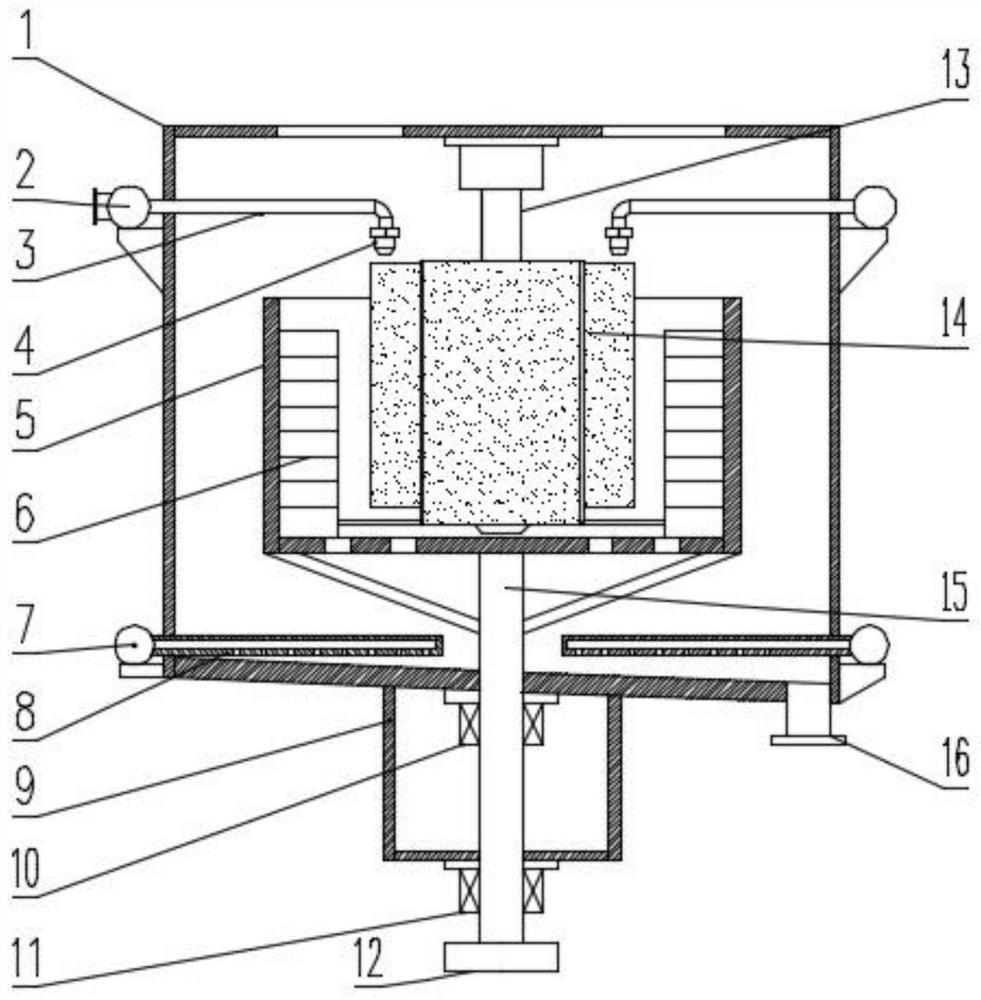
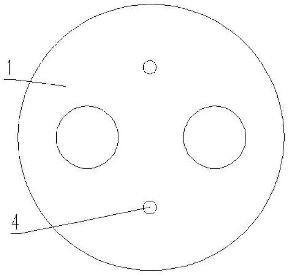
[0024] Embodiment one, see Figure 1-2 , an automatic cleaning equipment for automobile engine parts, comprising a cleaning box 1, a rotating box 5, and a fixed pipe 13, characterized in that: the rotating box 5 is arranged in the middle of the inner cavity of the cleaning box 1, and the upper end of the rotating box 5 is an opening Structure, the rotating box 5 is fixed on the upper end of the rotating shaft 15, the bottom plate of the rotating shaft 15 is provided with multiple groups of small holes, the inner wall of the rotating box 5 is fixed with a rotating brush 6, and the fixed tube 13 is inserted into the rotary box 5 along the center line of the rotary box 5, the outer side of the lower part of the fixed tube 13 is fixed with an adjustable brush 14, and the upper end of the fixed tube 13 is fixed at the center of the top plate of the cleaning box 1. A plurality of groups of spray nozzles 4 are arranged above the sides of the rotary box 5, and a plurality of groups of...

Embodiment 2

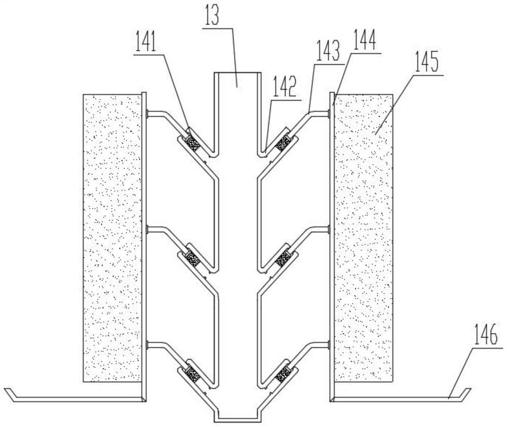
[0027] Embodiment two, see Figure 3-4 , an automatic cleaning device for automobile engine parts, comprising positioning tubes 142 arranged through the outer surface of the fixing tube 13 at a vertical position, and the positioning tubes 142 are arranged in a quartering circular arrangement from the top view angle of the fixing tube 13; In the positioning tube 142, a stopper 141 is movably embedded, and the stopper 141 can slide in the positioning tube 142 under the action of air pressure; The other end of the bristle fixing plate 144 is connected to the surface of the bristle fixing plate 144 at the vertical position; The bristle fixing plate 144 is led into the bristle fixing plate 144 at the elbow 143; the bristle fixing plate 144 has small holes uniformly penetrated at the fixing end surface of the bristles 145.

[0028] In this embodiment, air is pumped into the fixed tube 13 based on the air pump, so that when the positioning tube 142 is connected to the fixed tube 13,...

Embodiment 3

[0030] Embodiment three, see Figure 5-6 , an automatic cleaning device for automotive engine parts, comprising a plug tube 1411, a spherical shell 1412 and a back-stopping conical cover 1413, the plug tube 1411 is embedded with a back-stopping conical cover 1413, and the inner side of the back-stopping conical cover 1413 is The cavity is set, and the top of the back-stopping conical cover 1413 is a dense tip; the outer edge of the bottom end of the back-stopping cone cover 1413 is in a state of being connected with the inner edge of the bottom end of the plug tube 1411, and the airflow is self-blocking back into a conical shape. The cover 1413 guides the flow into the elbow 143; the tip of the anti-return conical cover 1413 is connected with a spherical shell 1412 at a symmetrical position, and the surface of the spherical shell 1412 is penetrated with air holes, and the blowing direction of the air holes is the resistance. Back to the connecting position of the conical cover...


PUM


Abstract

The invention discloses an automatic cleaning equipment for automobile engine parts, which is characterized in that: a rotary box is arranged in the middle of the inner cavity of the cleaning box, the upper end of the rotary box is an open structure, the rotary box is fixed on the upper end of the rotary shaft, and the bottom plate of the rotary shaft is provided with a There are several sets of small holes, and the rotating brush is fixed on the inner wall of the rotating box. The fixed shaft is inserted into the rotating box along the center line of the rotating box. In the center of the top plate of the cleaning box, there are multiple sets of nozzles above the sides of the rotating box, multiple sets of horizontal aeration tubes are set at the bottom of the cleaning tank, and multiple sets of aeration holes are set at the bottom of the aeration tubes. The invention has the advantages of good cleaning effect and high cleaning efficiency.

Description

technical field [0001] The invention belongs to the technical field of automobile maintenance, and in particular relates to automatic cleaning equipment for automobile engine parts. Background technique [0002] The rapid growth of automobile ownership has laid a solid foundation for the development of the automobile maintenance industry and brought huge business opportunities to the automobile maintenance industry. The engine is the heart of the car. After driving for a long time, the parts of the engine need to be cleaned. The prior art mainly uses high-pressure water for washing, and the washing efficiency is low, and the cleaning effect is not good. Contents of the invention [0003] The purpose of the present invention is to overcome the above-mentioned deficiencies in the prior art, and to provide an automatic cleaning equipment for automobile engine parts. [0004] An automatic cleaning equipment for automobile engine parts, comprising a cleaning box, a rotary box,...

Claims


Application Information

Patent Timeline
Patent Type & Authority Patents(China)
IPC IPC(8): B08B1/02B08B3/02B08B3/10B08B13/00
CPCB08B1/002B08B1/02B08B3/022B08B3/10B08B13/00
Inventor 洪彬彬骆惠珍
Owner 山东高新创达科技创业服务有限公司
Why Eureka
Try Eureka