Code nail driving device

A technology of coding nails and nail bases, applied in the field of coding nails, can solve the problems of high labor cost and low work efficiency.

Active Publication Date: 2021-03-19
GUANGZHOU HUAXINKE ENTERPRISE
View PDF9 Cites 2 Cited by
  • Summary
  • Abstract
  • Description
  • Claims
  • Application Information

AI Technical Summary

Problems solved by technology

However, the traditional coding nailing device generally needs to be held and lifted by the staff. After adjusting the height and position so that the

Method used


Image

  • Code nail driving device
  • Code nail driving device
  • Code nail driving device

Examples


Embodiment Construction

[0035] In order to make the above objects, features and advantages of the present invention more comprehensible, specific implementations of the present invention will be described in detail below in conjunction with the accompanying drawings. In the following description, numerous specific details are set forth in order to provide a thorough understanding of the present invention. However, the present invention can be implemented in many other ways different from those described here, and those skilled in the art can make similar improvements without departing from the connotation of the present invention, so the present invention is not limited by the specific embodiments disclosed below.

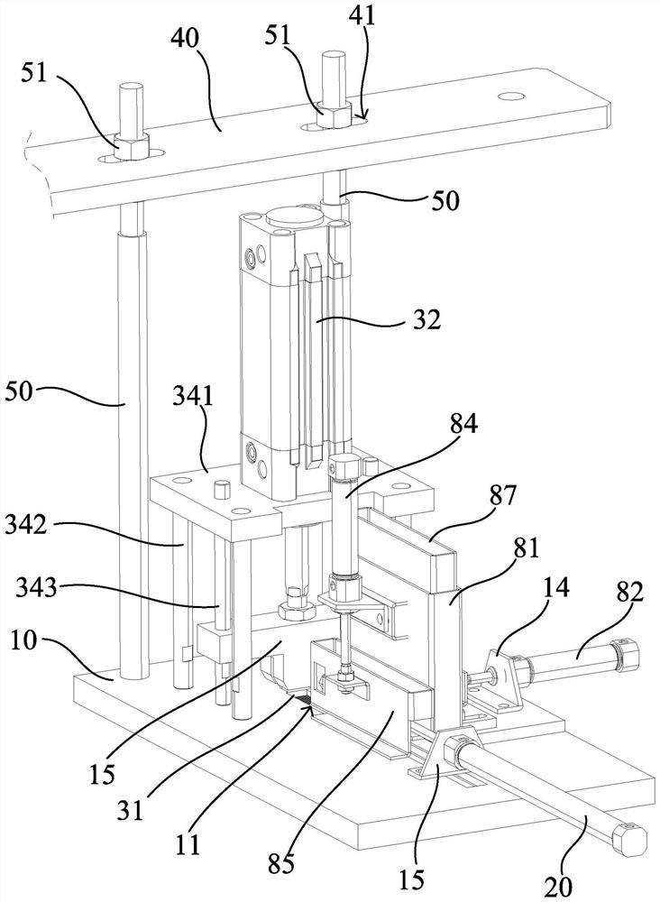
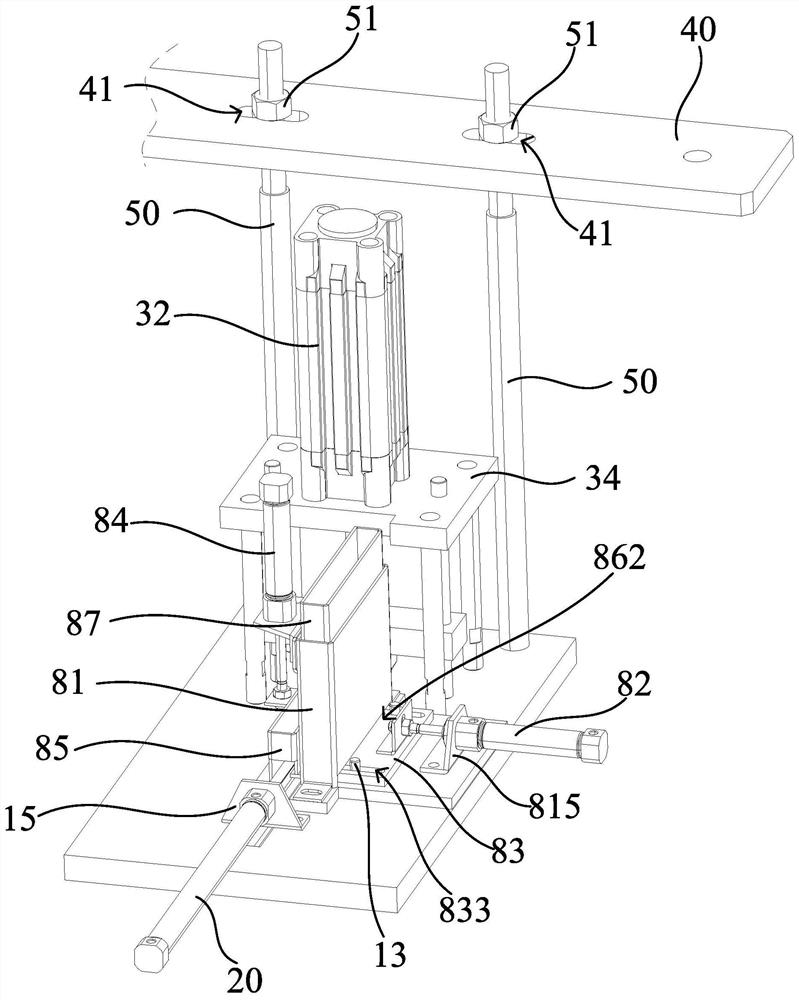
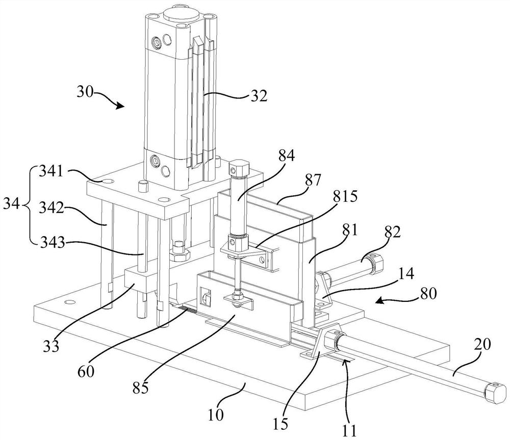
[0036] refer to figure 1 and figure 2 , figure 1 Schematically shows the structural diagram of one of the viewing angles of the coding nail device according to an embodiment of the present invention, figure 2 A structural diagram of another viewing angle of a coding nail device accor...


PUM


Abstract

The invention relates to a code nail driving device. The code nail driving device comprises a mounting base, a first push-pull mechanism, a nail driving assembly, a mounting plate and an adjusting rod; the mounting base is provided with a conveying groove used for conveying a code nail row; a nail driving window is formed in the bottom wall of one end of the conveying groove; the first push-pull mechanism is arranged at the other end of the conveying groove and is used for driving the code nail row in the conveying groove to move to the nail driving window along the conveying groove; the naildriving assembly comprises a nail driving head; the nail driving head is arranged opposite to the nail driving window and is used for driving code nails located at the nail driving window into presetparts; the mounting plate is fixedly mounted on a supporting structure; and the adjusting rod is adjustably arranged on the mounting plate and is connected with the mounting base. According to the code nail driving device, the code nails can be automatically mounted in the preset parts in batches, the working efficiency is relatively high, the automation degree is relatively high, and the labor cost is saved.

Description

technical field [0001] The invention relates to the technical field of coding nails, in particular to a coding nail device. Background technique [0002] In the traditional technology, for example, in some specific scenarios, when sheet-like plates or coils are used flatly, adjacent plates or coils need to be fixedly connected together by coding nails, usually using manual nail guns or pneumatic nails. The coding nail gun is used to fix the coding nails on the seam. However, the traditional coding nailing device generally needs to be held and lifted by the staff, and the height position is adjusted so that the nailing window is relative to the preset position, and then the nailing operation is performed manually. The work efficiency is low and the manpower higher cost. Contents of the invention [0003] Based on this, it is necessary to overcome the defects of the prior art and provide a coding nailing device, which can improve nailing efficiency, has a high degree of au...

Claims


Application Information

Patent Timeline
IPC IPC(8): B27F7/02B27F7/13
CPCB27F7/02B27F7/13
Inventor 赖燕根连嘉鑫覃昌壬杨智韬
Owner GUANGZHOU HUAXINKE ENTERPRISE
Why Eureka
Try Eureka