Device for filtering liquid drawn in between two superimposed layers of filtering media

A technology of filter device and filter medium, which can be used in filter separation, exhaust device, muffler device, etc., and can solve problems such as reducing efficiency and easily polluting catalytic converters.

Active Publication Date: 2021-03-26
VTESCO TECH GMBH
View PDF7 Cites 0 Cited by
  • Summary
  • Abstract
  • Description
  • Claims
  • Application Information

AI Technical Summary

Problems solved by technology

This is because certain impurities tend to contaminate the catalytic converter and thus reduce its efficiency

Method used


Image

  • Device for filtering liquid drawn in between two superimposed layers of filtering media
  • Device for filtering liquid drawn in between two superimposed layers of filtering media
  • Device for filtering liquid drawn in between two superimposed layers of filtering media

Examples


Embodiment Construction

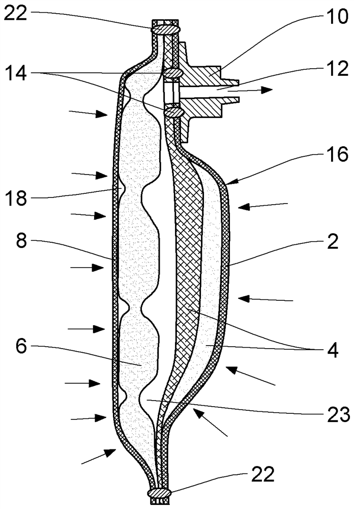
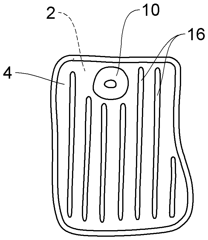
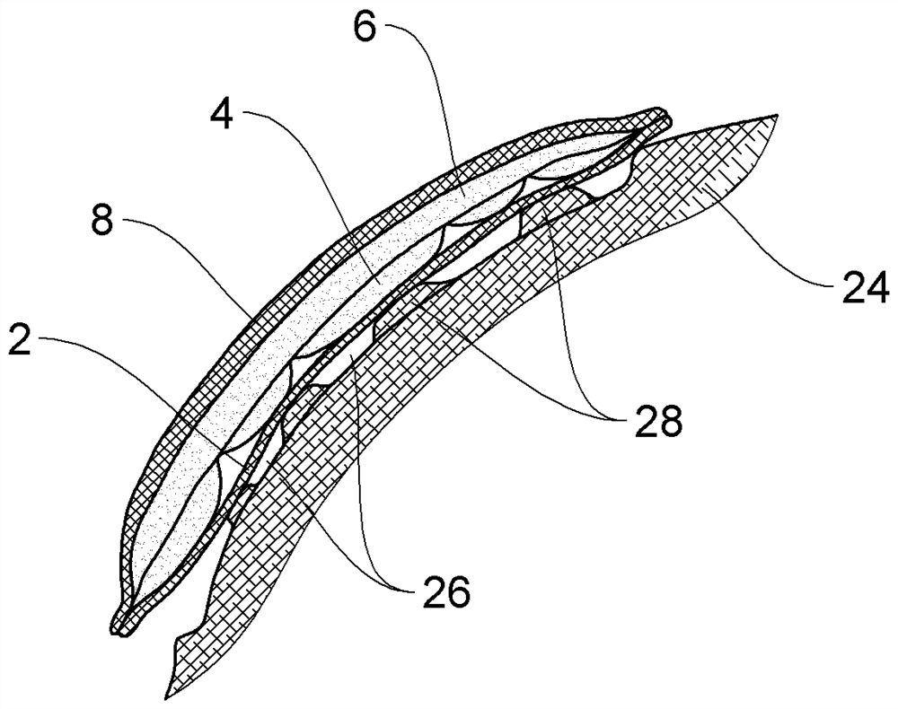
[0025] exist figure 1 , a longitudinal sectional view of a filter device showing a first outer surface 2 , a first filter layer 4 , a second filter layer 6 , a second outer surface 8 and an inlet connector 10 .

[0026] The filter device shown here is intended to be located, for example, in an additive reservoir of a motor vehicle. More specifically, it is eg a filter for urea solutions known under the name AUS32 or the registered trademark ADBLUE. The inlet connector 10 of the filter device can thus be mounted on the outlet hole of the reservoir so that all liquid leaving the reservoir passes through said filter device.

[0027] In a novel way, the filter device proposed here is realized as a stack of four filter layers welded together around their perimeters.

[0028] In general, in this specification, a weld may be produced, for example, by ultrasonic welding, using the width of the sonotrode-enclume assembly to define the width of the resulting wall. The use of such ult...


PUM


Abstract

The present invention relates to a filtration device for a liquid, comprising: at least two superimposed layers (4, 6) of filtering media which have weld lines (16, 18) together forming bands, the layers (4, 6) of filtering media having weld lines (16, 18) which are superimposed in such a manner that the weld lines (16, 18) of one layer (4, 6) form with the weld lines (18, 16) of the other layer (6, 4) a mesh in a view normal to the layers (4, 6) of filtering media, a first external face (2) and a second external face (8) which are each at least locally produced from a material which is water-permeable, the layers (4, 6) of filtering media being arranged between the external faces (2, 8) and an intake connector (10) which serves to draw in liquid through the filtration device.

Description

technical field [0001] The invention relates to a filter device for liquids. The device is more particularly intended for the purification of additives used in internal combustion engines in order to limit the pollutant emissions of this engine. Background technique [0002] For about 20 years, certain vehicles powered by internal combustion engines have been equipped with reservoirs intended to be filled with a solution containing urea. The solutions used are known from reference AUS32. It is a 32.5% dilution of urea in water. This urea is converted into ammonia, and then undergoes selective catalytic reduction (abbreviated as SCR in English, corresponding to SelectiveCatalytic Reduction) in a catalytic converter. The ammonia then makes it possible to reduce the NOx-type components present in the exhaust gas to nitrogen and water. [0003] Prior to use, the AUS32 type solution needs to be filtered to ensure that it is free of impurities which may enter the reservoir, eg...

Claims


Application Information

Patent Timeline
Patent Type & Authority Applications(China)
IPC IPC(8): B01D35/027B01D35/18B01D29/11B01D29/54B01D29/58
CPCB01D29/111B01D29/54B01D29/58B01D35/0273B01D35/18F01N3/2066F01N2610/02F01N2610/1406F01N2610/1426
Inventor G·马古因
Owner VTESCO TECH GMBH
Why Eureka
Try Eureka