ink cartridge

A technology of ink cartridges and ink sacs, which is applied in printing and other directions, can solve the problems of collision damage to the inkjet head, difficulty in clamping and positioning the cartridge body, and reduced strength of the cartridge body, so as to achieve cost saving, prolong service life, and simple processing technology.

Active Publication Date: 2021-12-17
SPEED INFOTECH (BEIHAI) COMPANY LIMITED
View PDF9 Cites 0 Cited by
  • Summary
  • Abstract
  • Description
  • Claims
  • Application Information

AI Technical Summary

Problems solved by technology

When the corresponding connection structure is processed on the box body, the strength of the box body will be reduced. At the same time, when the connection structure is processed on the box body with an inkjet head, it is not easy to clamp and position the box body, and it may also be damaged by collision inkjet head

Method used


Image

  • ink cartridge
  • ink cartridge
  • ink cartridge

Examples


Embodiment 1

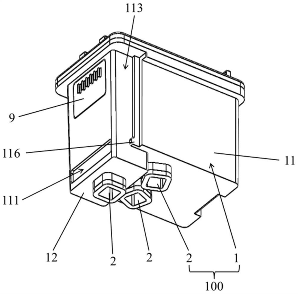
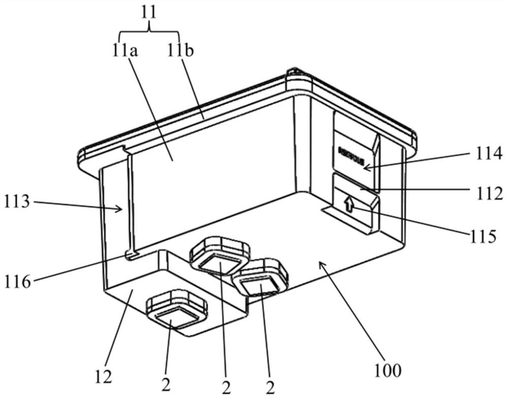
[0085] Such as Figure 1-Figure 5 As shown, the present embodiment provides an ink bag assembly, including an ink bag 100 and a protective member 200 . The ink bag 100 includes an ink bag body 1 and an ink outlet assembly 2 . The ink bag body 1 includes an ink storage cavity 117 for storing ink. The ink inlet of the ink outlet assembly 2 communicates with the ink storage chamber 117 . Exemplarily, the ink outlet assembly 2 is arranged at the bottom of the ink bag body 1, and the ink in the ink storage chamber 117 can flow into the ink outlet assembly 2 from the ink inlet of the ink outlet assembly 2 under the action of gravity. The protective member 200 in this embodiment is detachably connected to the ink bag 100 . During the transportation or storage of the ink bag 100 , the protective member 200 is installed on the ink bag 100 and seals the ink outlet of the ink outlet assembly 2 to effectively prevent ink leakage. When the ink bag 100 needs to be used, the protective m...

Embodiment 2

[0132] Such as Figure 22 and Figure 23 As shown, the difference between the present embodiment and the first embodiment lies in that the structure of the ink outlet assembly 2 is different. The ink outlet assembly 2 of this embodiment includes a connecting sleeve 22 and an ink absorbing member 21 . The connecting sleeve 22 is sleeved on the outside of the ink absorbing member 21 . The connecting sleeve 22 includes a sleeve body 221 and a connecting portion 222 . The sleeve body 221 is a hollow structure with openings at both ends, and the sleeve body 221 is sleeved on the outside of the ink absorbing member 21 . One end of the sleeve body 221 extends into the ink storage chamber 117 from the ink outlet opening of the ink storage chamber 117 . The connecting portion 222 is connected to an end of the sleeve body 221 outside the ink storage chamber 117 . Both the size of the connecting portion 222 and the sleeve body 221 are larger than the size of the ink outlet opening, ...

Embodiment 3

[0134] Such as Figure 24-Figure 28 As shown, the difference between the present embodiment and the first embodiment lies in that the structure of the ink outlet assembly 2 is different. The ink outlet assembly 2 of this embodiment includes a connecting sleeve 22 and an ink absorbing member 21 . The connection sleeve 22 includes a first sleeve body portion 2211 and a second sleeve body portion 2212 connected together. The size of the first set body part 2211 is larger than the size of the second set body part 2212 and the ink absorbing member 21 . On the outer wall of the ink bag body 1 , a fixing portion 13 protrudes from the ink outlet opening of the ink storage cavity 117 . The fixing part 13 is annular and arranged along the circumferential direction of the ink outlet opening. On the ink bag body 1 , an escape groove 14 is provided on the outer circumference of the fixing portion 13 . The first set body part 2211 protrudes into the escape groove 14 and is tightly fitte...


PUM


Abstract

The invention belongs to the field of printing equipment and discloses an ink box. The ink cartridge includes an ink bag and a box body, the box body is provided with an inkjet head and a mounting part, the ink bag is detachably connected to the mounting part, the ink bag includes an ink bag body and an ink outlet assembly, and the ink bag body includes an ink bag for storing In the ink storage chamber of the ink, the ink inlet of the ink outlet assembly is connected with the ink storage chamber, and the ink outlet of the ink outlet assembly is connected with the ink inlet of the inkjet head. In the present invention, the ink bag is installed on the mounting part, so as to realize the connection between the ink bag and the box body. The ink sac is connected to the box body through the mounting piece, and there is no need to process a connection structure on the box body to cooperate with the ink sac, so as to ensure the strength of the box body and avoid damage to the inkjet head at the same time.

Description

technical field [0001] The invention relates to the field of printing equipment, in particular to an ink cartridge. Background technique [0002] With the gradual popularization of automated office equipment, printing equipment plays an increasingly important role in people's normal work and study. Among them, inkjet printing equipment has been favored for its advantages of low energy consumption, no pollution and easy color printing. users' favor. [0003] An ink cartridge of an inkjet printing device generally consists of a cartridge body and an ink bag. The ink bag is a replaceable consumable, and the ink bag is usually inserted into the box body. In order to fixedly connect the ink bag and the box body, a connecting structure that cooperates with each other is provided on the box body and the ink bag. When the corresponding connection structure is processed on the box body, the strength of the box body will be reduced. At the same time, when the connection structure is...

Claims


Application Information

Patent Timeline
Patent Type & Authority Patents(China)
IPC IPC(8): B41J2/175
CPCB41J2/17503B41J2/17513B41J2/17523
Inventor 赵晨海何景华刘敏章恒
Owner SPEED INFOTECH (BEIHAI) COMPANY LIMITED
Why Eureka
Try Eureka