Cast bearing ring taking-out device

A technology for taking out devices and bearing rings, applied in the direction of lifting devices, crowbars, etc., can solve problems such as prone to accidents and dangers, and achieve the effects of reducing threats, uniform distribution, and labor-saving movement of bearing rings

Inactive Publication Date: 2021-06-01
李洪玉
View PDF5 Cites 0 Cited by
  • Summary
  • Abstract
  • Description
  • Claims
  • Application Information

AI Technical Summary

Problems solved by technology

[0003] In the centrifugal casting process of the bearing ring, after it is cast by the centrifugal casting machine, people need to use tools such as steel hooks to hook it out. Since the casting is not long after forming, and it is in a high temperature state, the whole body is red hot. This process often More dangerous, prone to accidents

Method used


Image

  • Cast bearing ring taking-out device
  • Cast bearing ring taking-out device
  • Cast bearing ring taking-out device

Examples


Embodiment 1

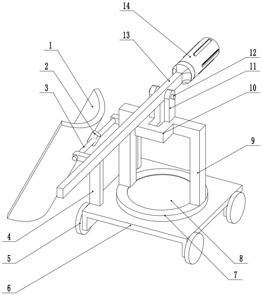
[0019] A casting bearing ring removal device, including a slide plate 1, a mounting block 2, a rotating shaft 3, a support frame 4, a wheel 5, a bottom plate 6, a turntable 7, a positioning rotating column 8, a support frame 2 9, a concave frame 10, and a support frame Three 11, rotating shaft 2 12, lever 13 and internal expansion assembly 14, the back of the slide plate 1 is provided with a mounting block 2, and the mounting block 2 is equipped with a rotating shaft 1 3, and the rotating shaft 1 3 is installed on the support frame, so The support frame one 4 is arranged on the base plate 6, the bottom of the base plate 6 is provided with a wheel 5, the middle position of the base plate 6 is provided with a positioning rotating column 8, and the outer circumference of the positioning rotating column 8 is equipped with a turntable 7, so The turntable 7 is provided with a support frame 2 9, the middle position of the support frame 2 9 is provided with a concave frame 10, the top ...

Embodiment 2

[0022] A casting bearing ring removal device, including a slide plate 1, a mounting block 2, a rotating shaft 3, a support frame 4, a wheel 5, a bottom plate 6, a turntable 7, a positioning rotating column 8, a support frame 2 9, a concave frame 10, and a support frame Three 11, rotating shaft 2 12, lever 13 and internal expansion assembly 14, the back of the slide plate 1 is provided with a mounting block 2, and the mounting block 2 is equipped with a rotating shaft 1 3, and the rotating shaft 1 3 is installed on the support frame, so The support frame one 4 is arranged on the base plate 6, the bottom of the base plate 6 is provided with a wheel 5, the middle position of the base plate 6 is provided with a positioning rotating column 8, and the outer circumference of the positioning rotating column 8 is equipped with a turntable 7, so The turntable 7 is provided with a support frame 2 9, the middle position of the support frame 2 9 is provided with a concave frame 10, the top ...


PUM


Abstract

The invention relates to a cast bearing ring taking-out device, and belongs to the field of bearing casting equipment. The cast bearing ring taking-out device comprises a sliding plate, a mounting block, a first rotating shaft, a first supporting frame, wheels, a bottom plate, a rotating disc, a positioning rotating column, a second supporting frame, a concave frame, a third supporting frame, a second rotating shaft, a lever and an internal expansion assembly; the mounting block is arranged on the back of the sliding plate, the mounting block is matched with the first rotating shaft, the first rotating shaft is mounted on the supporting frame, and the first supporting frame is arranged on the bottom plate; and the wheels are arranged at the bottom of the bottom plate, the positioning rotating column is arranged in the middle of the bottom plate, the rotating disc is arranged on the periphery of the positioning rotating column in a matched manner, the second supporting frame is arranged on the rotating disc, and the concave frame is arranged in the middle of the second supporting frame. Through cooperation of the internal expansion assembly and the lever, a bearing ring can be rapidly taken out, and the situation that sliding happens due to excessive stress caused by too small contact area, the inner wall of the bearing ring is damaged, and even the equipment structure is damaged is avoided.

Description

technical field [0001] The invention relates to a device for taking out a casting bearing ring, which belongs to the field of bearing casting equipment. Background technique [0002] For some larger bearing outer rings, it is usually produced by centrifugal casting. Centrifugal casting is a technology and method that injects liquid metal into a high-speed rotating mold, and makes the molten metal centrifugally move to fill the mold and form a casting. Due to the centrifugal movement, the liquid metal can fill the mold well in the radial direction and form the free surface of the casting; a cylindrical inner hole can be obtained without a core; it is helpful for the removal of gas and inclusions in the liquid metal; it affects the metal Crystallization process, thereby improving the mechanical and physical properties of the casting. [0003] In the centrifugal casting process of the bearing ring, after it is cast by the centrifugal casting machine, people need to use tools s...

Claims


Application Information

Patent Timeline
Patent Type & Authority Applications(China)
IPC IPC(8): B66F15/00B22D13/10
CPCB66F15/00B22D13/108
Inventor 李洪玉
Owner 李洪玉
Why Eureka
Try Eureka