

Nasal shaper
A technology of plasticizer and nostrils, applied in medical science and other fields
- Summary
- Abstract
- Description
- Claims
- Application Information
AI Technical Summary
Problems solved by technology
Method used
Image

Examples
Embodiment Construction
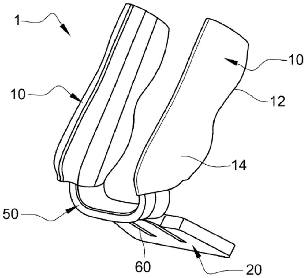
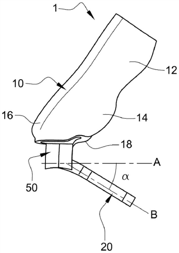
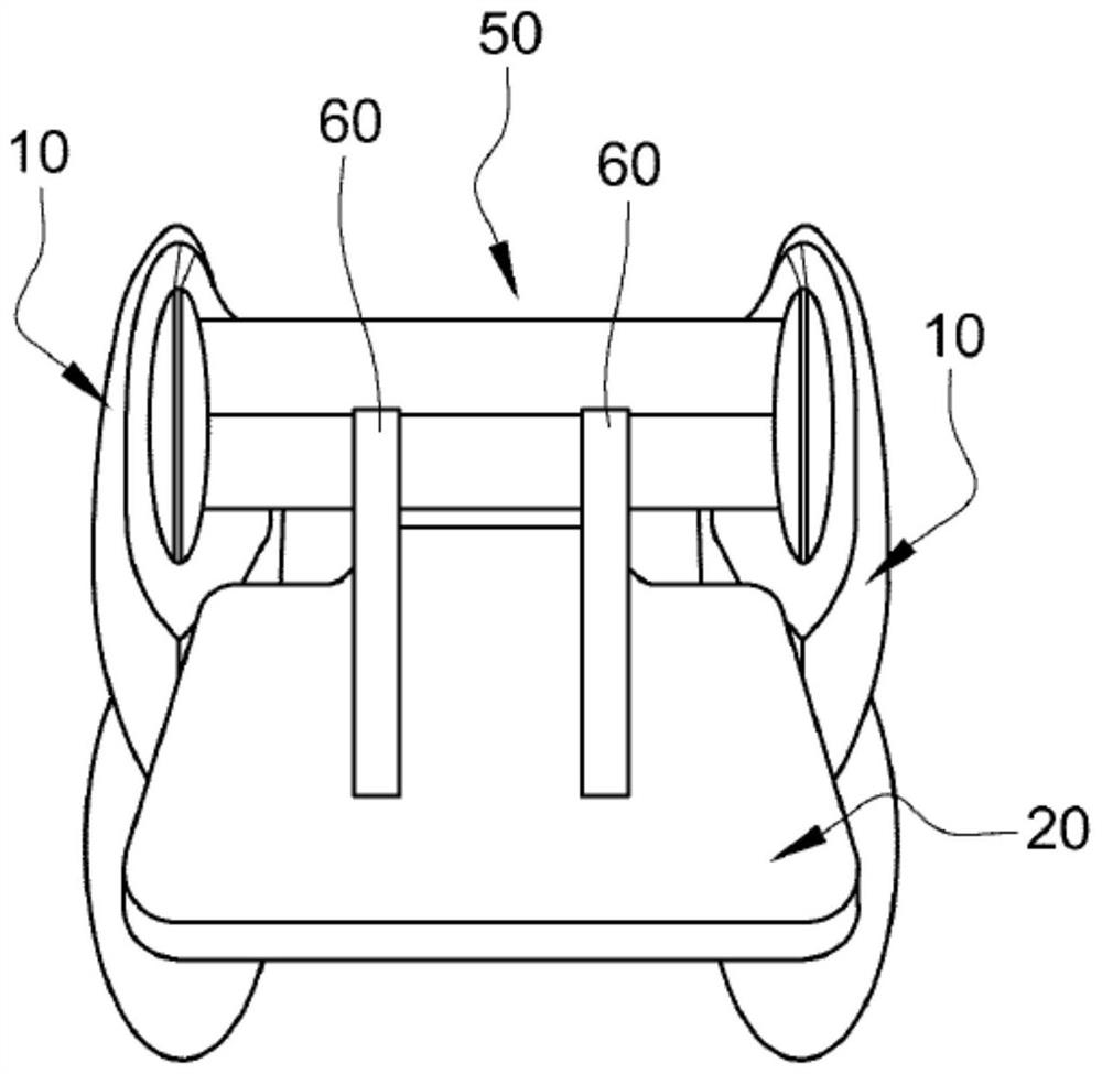
[0037] exist Figure 1 to Figure 3 A nostril shaper according to a first embodiment of the invention is shown in , indicated with the overall reference numeral 1 .
[0038] Such nostril shapers are typically used after rhinoplasty. The most frequent use of a nostril shaper1 is after reconstructive surgery for a cleft lip and palate in children. Following this type of surgery, the purpose of using a nostril shaper is to shape the subject's nostrils to the shape preset by the surgeon while allowing them to breathe and, in the case of infants, to easily suck and feed. On the other hand, according to the principle of pressure therapy, as explained in detail below, the present nostril shaper has the advantage that it achieves a better appearance of scars than scars obtained with prior art shapers.
[0039] Figure 1 to Figure 3 The nostril shaper 1 shown in includes two tubes 10 intended to be inserted into the nostrils of a subject. The tubes 10 are connected to each other by ...
PUM
 Abstract
Description
Claims
Application Information