Axial flow fan device

An axial flow fan and fan technology, which is applied to pump devices, components of pumping devices for elastic fluids, mechanical equipment, etc., can solve the problems of large space requirements, large size, large load, etc. Reduced space requirements, reduced vibration and noise levels, reduced load effects

Active Publication Date: 2021-08-17
杭州智新机电设计有限公司
View PDF5 Cites 0 Cited by
  • Summary
  • Abstract
  • Description
  • Claims
  • Application Information

AI Technical Summary

Problems solved by technology

[0004] The air volume, air pressure and rotational speed of the traditional stand-alone fan are designed by a column motor to drive the impeller to rotate. In order to meet this design requirement, the size of the column motor is relatively large, which makes the size of the traditional fan too large and affects the use of space. The requirements are relatively large; and the impeller of the traditional single-stage fan has a large load in the working state, and this type of fan will generate a lot of noise when it is running.

Method used


Image

  • Axial flow fan device
  • Axial flow fan device
  • Axial flow fan device

Examples


Embodiment Construction

[0037] In order to enable those skilled in the art to better understand the solutions of the present invention, the technical solutions in the patent embodiments of the present invention will be described clearly and completely below with reference to the accompanying drawings in the patent embodiments of the present invention.

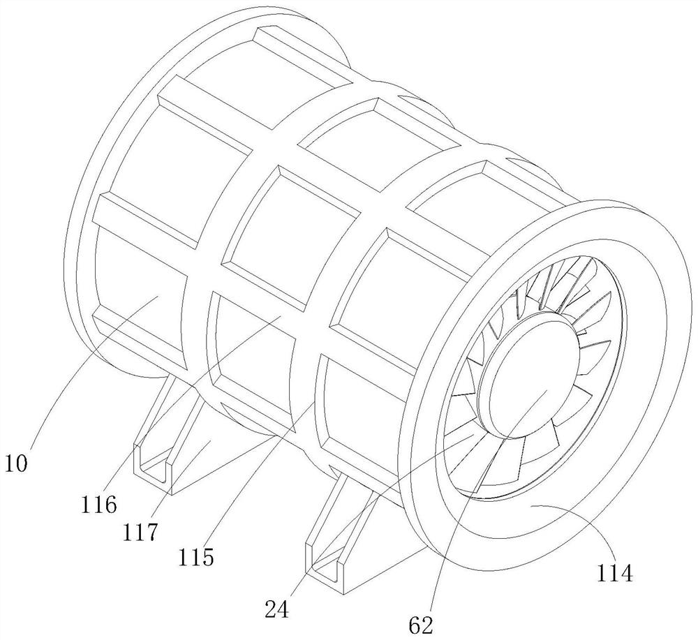
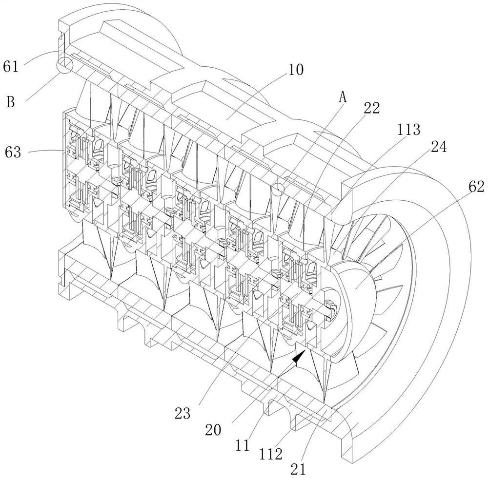
[0038] figure 1 Shown is an axial fan consisting of five separate fan modules connected in series, with the five fan modules located within the same fan housing. figure 2 A cross-sectional view along the axis A-A of Figures is shown, and shows a schematic diagram of five separate fan modules connected in series.

[0039] refer to figure 1 , figure 2 , the axial flow fan includes a fan casing 10 and five fan modules 20 connected in series with each other inside the fan casing 10 . After the five fan modules 20 are connected in series, the internal wind pressure of the axial flow fan 1 is increased. Five fan modules 20 are connected in series in t...


PUM


Abstract

The invention discloses an axial flow fan device. The device comprises a fan shell and a plurality of fan modules which are arranged in the fan shell and connected together in series. Each fan module comprises a flow guiding piece, an impeller and a disc-type motor, wherein the flow guiding piece is connected with the fan shell, and the flow guiding piece comprises a fixed cylinder connected with the fan shell and a guide vane arranged in the fixed cylinder; the impeller corresponds to the guide vane and is positioned on the air inlet side of the guide vane; the disc-type motor is arranged on the flow guiding piece, the disc-type motor comprises a stator provided with a winding, rotors provided with permanent magnets and an output shaft, the two rotors are arranged on the two sides of the stator respectively, the output shaft is connected with the rotors, and the output shaft is connected with the impeller. According to the axial flow fan device, as the multiple fan modules are arranged in the fan shell, the requirement on design parameters is achieved by connected the fan modules in series, and based on the working principle of the disc-type motor, the fan is made to be smaller and has lower requirement on space for use.

Description

technical field [0001] The invention belongs to the technical field of fans, in particular to an axial flow fan device. Background technique [0002] At present, as a ventilation device, the fan is a widely used representative mechanical device that increases the gas pressure and discharges the gas. The fan usually includes a casing and an impeller inside. The impeller is a rotating component and is fixed on the hub by a plurality of blades. Constructed above, the blades work in the fluid, and most fans are driven by column motors. [0003] In the traditional column motor structure, the stator is on the periphery and the rotor rotates in the middle, which makes the axial size of the column motor large; while the disc motor, also known as the butterfly motor, has the same working principle as the column motor, with a flat shape, The axial dimension is short and other characteristics, especially suitable for thin installation occasions. And the disc motor adopts an ironless ...

Claims


Application Information

Patent Timeline
Patent Type & Authority Applications(China)
IPC IPC(8): F04D25/08F04D29/056F04D29/54
CPCF04D25/08F04D29/542F04D29/056
Inventor 李诗徉叶豪杰蒋洪涛祁忠祥张子澄
Owner 杭州智新机电设计有限公司
Why Eureka
Try Eureka