An electromagnetic coil structure for an electromagnetic valve

An electromagnetic coil and solenoid valve technology, applied in the direction of transformer/inductor coil/winding/connection, transformer/inductor core, valve operation/release device, etc., can solve the complex structure of electromagnetic coil, unstable magnetic field force, Weak electromagnetic force and other problems, to achieve the effect of extensive use, compact structure and large magnetic field force

Active Publication Date: 2022-01-25
YUYAO SANLIXIN SOLENOID VALVE CO LTD
View PDF15 Cites 0 Cited by
  • Summary
  • Abstract
  • Description
  • Claims
  • Application Information

AI Technical Summary

Problems solved by technology

[0005] The problem to be solved by the present invention is to provide an electromagnetic coil structure for electromagnetic valves to overcome the defects of complex structure, large volume, unstable magnetic field force and weak electromagnetic force of existing electromagnetic coils.

Method used


Image

  • An electromagnetic coil structure for an electromagnetic valve
  • An electromagnetic coil structure for an electromagnetic valve
  • An electromagnetic coil structure for an electromagnetic valve

Examples


Embodiment Construction

[0027] The specific implementation manners of the present invention will be further described in detail below in conjunction with the accompanying drawings and embodiments. The following examples are used to illustrate the present invention, but are not intended to limit the scope of the present invention.

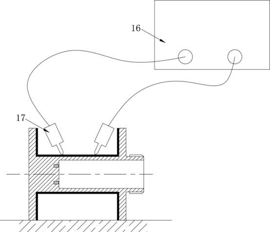
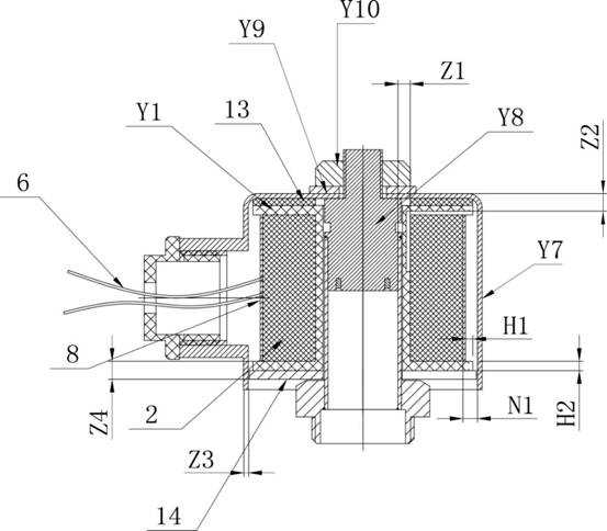
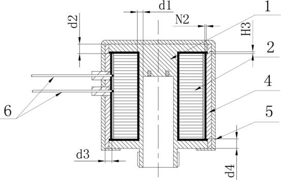
[0028] refer to Figure 1 to Figure 8 , The present invention provides an electromagnetic coil structure for an electromagnetic valve, including an integral coil frame 1 , coil winding 2 , magnetically permeable casing 4 and lead wire 6 . The coil frame 1 is provided with a winding part 101, the inner wall of the winding part 101 is sprayed with an insulating layer 3, the coil winding 2 is wound on the winding part 101, and the insulating layer 3 is used to keep the coil winding 2 and the coil frame 1 insulated The outer side of the coil winding 2 is equipped with a magnetic shell 4, and the outer side of the magnetic shell 4 is provided with a lead wire 6, and the lead w...


PUM


Abstract

The invention provides an electromagnetic coil structure for an electromagnetic valve, which includes a coil winding and an integrated coil frame. The coil frame is provided with a winding part, and an insulating layer is sprayed on the inner wall of the winding part. The coil winding is wound on the winding portion, and the insulating layer is used to keep the coil winding insulated from the coil frame; a magnetically permeable housing is installed on the outside of the coil winding, and the magnetically permeable housing A lead-out wire is provided on the outer side of the coil, and the lead-out wire is electrically connected to the coil winding through the magnetically permeable housing. The electromagnetic coil structure used in the electromagnetic valve provided by the invention overcomes the defects of complex structure, large volume, unstable magnetic field force and weak electromagnetic force of the existing electromagnetic coil.

Description

technical field [0001] The invention relates to the field of electromagnetic coils, in particular to an electromagnetic coil structure for an electromagnetic valve. Background technique [0002] The electromagnetic coil is wound on the insulating tube by a circle of wires, and the wires are insulated from each other. Electromagnetic coils are devices that use the principle of electromagnetic induction to work. When a current flows through a wire, a certain electromagnetic field will be generated around the wire, and the wire itself of this electromagnetic field will induce the wire within the range of this electromagnetic field. The solenoid coil is a main part of the solenoid valve, which is responsible for the opening and closing of the solenoid valve. [0003] The electromagnetic coil in the prior art is to wind the enameled wire on the skeleton made of insulating material. The top of the skeleton is equipped with an upper magnetic guide plate, and the bottom is equippe...

Claims


Application Information

Patent Timeline
Patent Type & Authority Patents(China)
IPC IPC(8): H01F27/02H01F27/24H01F27/28H01F27/30H01F27/32F16K31/06
CPCH01F27/306H01F27/324H01F27/24H01F27/02H01F27/2828F16K31/0675
Inventor 毛杉海邵杰鲁焕炯顾国云
Owner YUYAO SANLIXIN SOLENOID VALVE CO LTD
Why Eureka
Try Eureka