Coaxial cable tension test method

A tensile test, coaxial cable technology, applied in the direction of applying stable tension/pressure to test the strength of materials, measuring devices, instruments, etc. The effect of improving accuracy, improving tightness, and improving drawing efficiency

Pending Publication Date: 2021-11-09
SHENYU COMM TECH
View PDF7 Cites 1 Cited by
  • Summary
  • Abstract
  • Description
  • Claims
  • Application Information

AI Technical Summary

Problems solved by technology

[0003] When performing a tensile test on a cable, one of the displacement mechanisms of the general tensile test device moves, thereby affecting the test effect during the test, wasting test time, and the position of the cable to be tested cannot be adjusted according to the requirements during the tensile test , because the moving cable is cumbersome, which affects the stretching time and reduces the stretching efficiency. When used for a long time, the fastening mechanism of the general tensile test device will fatigue, and then reduce the fastening effect on the cable when stretching , thus affecting the accuracy of stretch data

Method used


Image

  • Coaxial cable tension test method
  • Coaxial cable tension test method
  • Coaxial cable tension test method

Examples


Embodiment 1

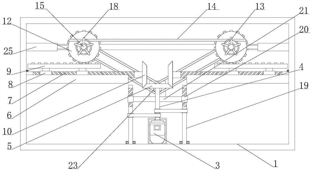
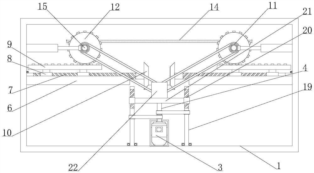
[0046] Example 1, please refer to Figure 1-7 , when the adjustment gear 12 moves in the opposite direction, the first transmission rod 4 drives the second rotating screw rod 19 to rotate through the crawler belt, so that the second sliding nut 20 on the surface of the second rotating screw rod 19 drives the second driving motor through the bearing plate 21 22 moves upwards, thereby keeping the distance between the second transmission rod 23 and the second installation rod 15, making it convenient for the second transmission rod 23 to drive the first installation rod 11 to rotate through the crawler belt, and when the adjustment gear 12 moves in the opposite direction, the adjustment rod The upper side of 9 will drive the adjustment gear 12 to rotate slowly in the opposite direction, and then the adjustment gear 12 will drive the first installation rod 11 to rotate slowly in the opposite direction, so that the track will rotate relatively on the surface of the first installatio...

Embodiment 2

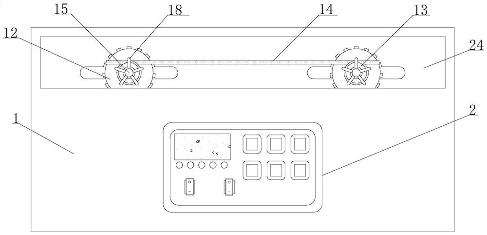
[0047] Example 2, please refer to Figure 1-7 , when the adjustment gear 12 moves in the opposite direction, the first installation rod 11 slides on the upper side of the isolation plate 24, and at the same time the other end of the second installation rod 15 slides on both sides of one end inside the housing 1 through the auxiliary wheel 17, so that When the adjusting gear 12 moves oppositely, the stability of the installation shaft 13 pulling the cable body 14 is improved.

[0048] Working principle: before use, power on the control panel 2, the first drive motor 3, the second drive motor 22, the first electric cylinder 16 and the second drive motor 22, and wrap the two ends of the cable body 14 to be detected on the The surface of the installation shaft 13 on both sides. At this time, the first electric cylinder 16 drives the second installation rod 15 to shrink, and then the second installation rod 15 clamps the cable body 14 on the surface of the installation shaft 13 thr...


PUM


Abstract

The invention discloses a coaxial cable tension test method. The two ends of a to-be-detected cable body are wound on the surfaces of mounting shafts on the two sides respectively; and a first sliding nut on the surface of the first rotating screw rod drives an adjusting rod to move relatively, so that the upper side of the adjusting rod drives adjusting gears to move oppositely, the distance between the adjusting gears is changed, and the purpose of stretching the cable body is achieved. A second driving motor is started, a second transmission rod rotates through a crawler belt and a first mounting rod, so that the first mounting rod drives a cable body to move through a mounting shaft, the position needing to be stretched is changed, the stretching part of the cable body can be adjusted according to requirements during testing, time and labor are saved, and therefore, the stretching efficiency of the cable body is improved during the test.

Description

technical field [0001] The invention relates to the technical field of cable tension test, in particular to a coaxial cable tension test method. Background technique [0002] The cable is usually a rope-like cable twisted by several or several groups of wires. Each group of wires is insulated from each other and is often twisted around a center. The entire outside is covered with a highly insulating covering. The cable has The characteristics of internal electrification and external insulation require a series of tests before the cable is used. The tensile testing machine is also known as the universal material testing machine. Universal testing machine is a mechanical testing machine used for static load, tension, compression, bending, shearing, tearing, peeling and other mechanical performance tests of instruments and equipment for various materials. It is suitable for plastic sheets, pipes, Various physical and mechanical performance tests of profiled materials, plastic ...

Claims


Application Information

Patent Timeline
Patent Type & Authority Applications(China)
IPC IPC(8): G01N3/08G01N3/02G01N3/04
CPCG01N3/08G01N3/02G01N3/04G01N2203/005G01N2203/028
Inventor 汤晓楠陈宏
Owner SHENYU COMM TECH
Why Eureka
Try Eureka