High-precision six-jaw duplex floating type self-centering clamping mechanism and clamping method

A self-centering clamping and floating technology, used in clamping, positioning devices, metal processing machinery parts, etc., can solve the problem of prolonging the labor time and labor intensity of processing workers, thin-walled parts easily deformed, and parts processing rigidity. It can overcome the problems of poor turning and other problems, and achieve the effect of overcoming the thermal deformation of turning, stable clamping and reduced processing difficulty.

Pending Publication Date: 2021-12-10
东风汽车动力零部件有限公司
View PDF13 Cites 2 Cited by
  • Summary
  • Abstract
  • Description
  • Claims
  • Application Information

AI Technical Summary

Problems solved by technology

[0003] Although there are a variety of positioning and clamping mechanisms used in turning finishing in the prior art, these clamping mechanisms generally adopt the traditional slider type or 3-6 jaw jaw type design, the parts have poor machining rigidity, and thin-walled parts It is prone to deformation, inaccurate positioning, poor tool change and tool setting accuracy, which increases the generation of work waste, causes great waste, and prolongs the labor time and labor intensity of processing workers
And the ordinary clamping mechanism has no pressure maintaining measures, so the safety is poor

Method used


Image

  • High-precision six-jaw duplex floating type self-centering clamping mechanism and clamping method
  • High-precision six-jaw duplex floating type self-centering clamping mechanism and clamping method
  • High-precision six-jaw duplex floating type self-centering clamping mechanism and clamping method

Examples


Embodiment Construction

[0032] The present invention will be further described in detail below in conjunction with the accompanying drawings and specific embodiments.

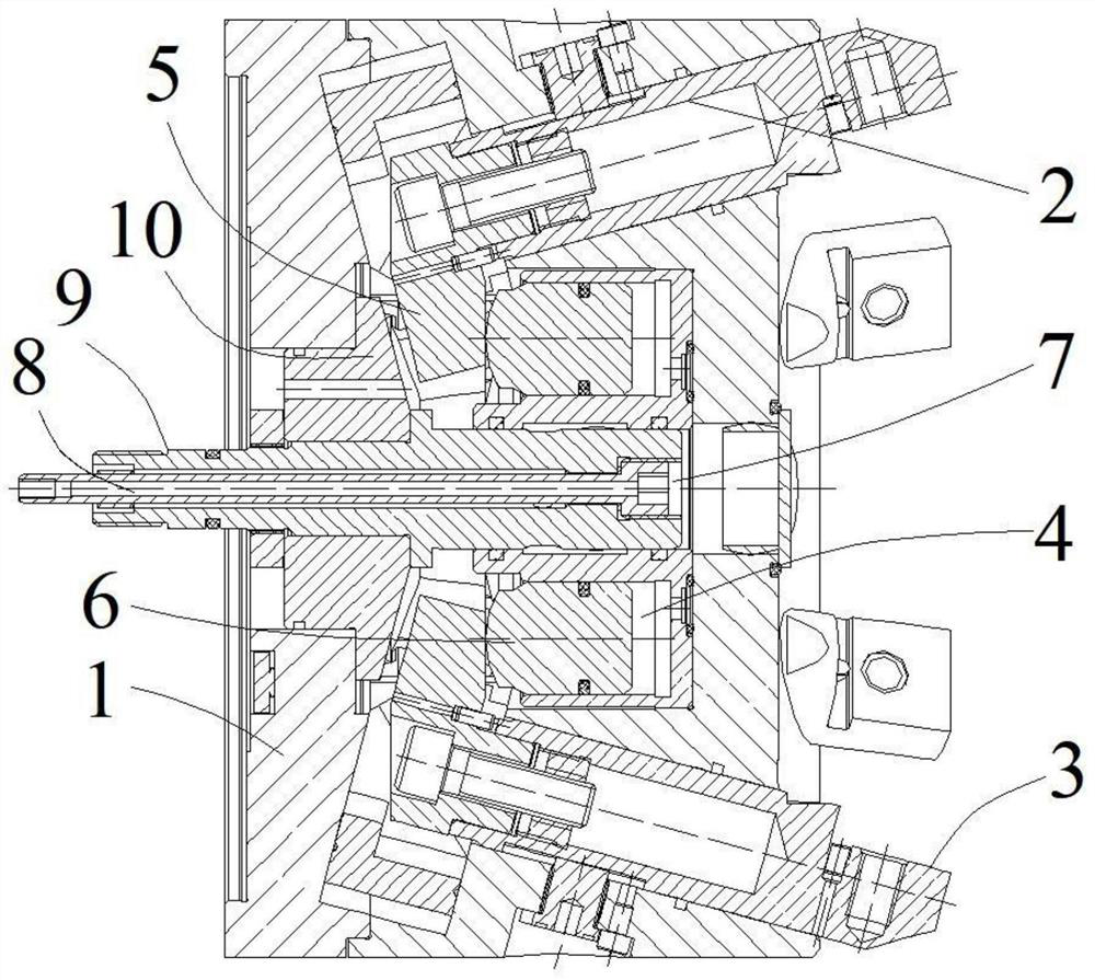
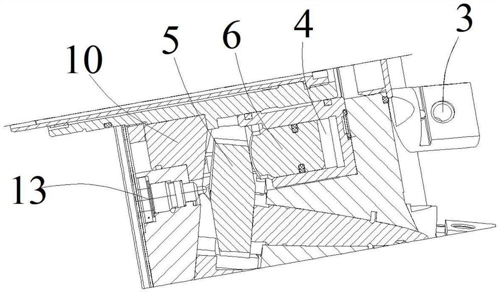
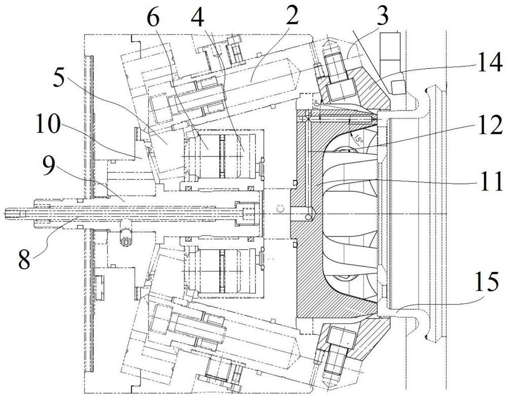
[0033] Such as Figure 1~4 As shown, the clamp of this embodiment includes a clamp body 1 on which two sets of jaws are arranged, each set of jaws includes three jaws, and each jaw includes a diagonal stay rod 2 pierced through the clamp body 1 . Such as Figure 1~3 As shown, the fixture body 1 of this embodiment is provided with installation grooves corresponding to the diagonal stay rods 2 one by one. The installation grooves are arranged obliquely. One end of the outer side of 1 is provided with a claw 3, and a clamping block 14 is installed on the claw 3, and the clamping block 14 is a block structure fixed on the claw 3 for enlarging the contact area with the workpiece.

[0034] One end of the oblique tie rod 2 of the present embodiment extending into the clamp body 1 is provided with a wedge 5, such as Figure 1~3 As shown, t...


PUM


Abstract

The invention relates to the technical field of clamp structures, in particular to a high-precision six-jaw duplex floating type self-centering clamping mechanism and a clamping method. The clamping mechanism comprises a clamp body and further comprises at least two sets of clamping jaws, and each set comprises at least three clamping jaws; an inclined mounting groove is formed in the clamp body; each clamping jaw comprises a diagonal draw bar, which is arranged in the mounting groove in a penetrating mode and can move in the length direction of the mounting groove, and a clamping jaw body, which is fixed to the end, extending out of the outer side of the clamp body, of the corresponding diagonal draw bar; plunger cylinders used for driving the diagonal draw bars to move along the mounting groove so as to tighten the clamping jaw bodies to clamp a workpiece are arranged in the clamp body; and the plunger cylinders are in one-to-one correspondence with the diagonal draw bars, the driving speeds of the corresponding plunger cylinders in the same set of clamping jaws are consistent, and the driving speeds of the plunger cylinders in different sets of clamping jaws are different. The clamp is simple in structure and convenient to operate, pre-clamping and pre-positioning of the workpiece are achieved by controlling the clamping speeds of different sets of clamping jaws, the clamping precision of the workpiece is improved, and the technical problem of turning thermal deformation is solved.

Description

technical field [0001] The invention relates to the technical field of clamp structures, in particular to a high-precision six-claw double-connected floating self-centering clamping mechanism and a clamping method. Background technique [0002] In the automobile braking system, the car brake disc is a precision part in the brake parts, and the dimensional accuracy is high, especially the thickness difference of the brake disc cap surface is usually only 5-6mm, and the clamping and turning processing are easy to produce Clamping and turning thermal deformation, the flatness of the wheel and hub mounting surface is required to be 0.02mm, and the runout is required to be 0.025mm. These high-precision shape and position tolerances are a major problem in brake disc processing. In order to meet the above size and shape tolerance requirements, this requires high-precision, high-strength, high-sensitivity positioning and processing methods to achieve. Various dimensions are processe...

Claims


Application Information

Patent Timeline
Patent Type & Authority Applications(China)
IPC IPC(8): B23Q3/00
CPCB23Q3/00
Inventor 汪铁云余涛叶辛陈强高云
Owner 东风汽车动力零部件有限公司
Why Eureka
Try Eureka