Die plate groove punching machine for chip machining

A template groove and stamping machine technology, applied in metal processing equipment, manufacturing tools, feeding devices, etc., can solve the problems of inability to perform continuous stamping, inability to complete automatic unloading and loading, slow stamping speed, etc.

Inactive Publication Date: 2022-01-11
黄高升
View PDF0 Cites 2 Cited by
  • Summary
  • Abstract
  • Description
  • Claims
  • Application Information

AI Technical Summary

Problems solved by technology

[0004] Aiming at the deficiencies of the prior art, the present invention provides a template groove stamping machine for chip processing, which solves the problems that the stamping machine cannot complete automatic unloading and loading when the stamping machine is working, the stamping speed is relatively slow, and continuous stamping cannot be performed.

Method used


Image

  • Die plate groove punching machine for chip machining
  • Die plate groove punching machine for chip machining
  • Die plate groove punching machine for chip machining

Examples


Embodiment Construction

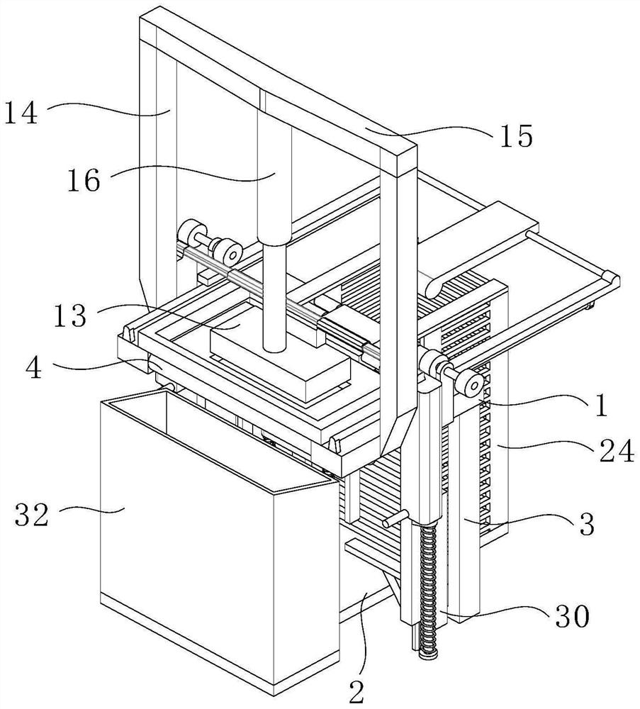
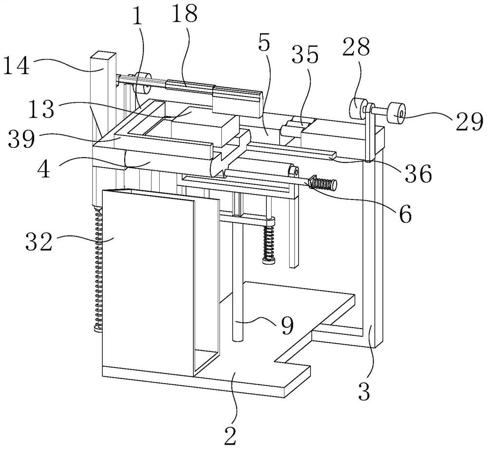
[0024] Such as Figure 1-5 As shown, a template groove stamping machine for chip processing includes a workbench 1 and a support platform 2, the workbench 1 is located above the support platform 2, and the workbench 1 and the support platform 2 are fixedly connected by two support frames 3. The upper surface of the table 1 is provided with a through hole 5, and the inside of the through hole 5 is provided with a shaping block 4, the bottom surface of the workbench 1 is elastically hinged with a support shaft 6, and the bottom surface of the shaping block 4 is fixedly sleeved on the outer surface of the support shaft 6, The support shaft 6 is positioned in front of the central axis of the shaping block 4, and the upper surface of the shaping block 4 is lower than the upper surface of the workbench 1, so that the material is positioned in the through hole 5, and the upper surface of the workbench 1 is fixedly connected with a positioning frame 39 for positioning. The frame 39 is...


PUM


Abstract

The invention provides a die plate groove punching machine for chip machining, and relates to the field of chip machining. The die plate groove punching machine for chip machining comprises a workbench and a supporting table, the workbench is located above the supporting table, the workbench and the supporting table are fixedly connected through two supporting frames, a through hole is formed in the upper surface of the workbench, a shaping block is arranged in the through hole, a supporting shaft is elastically hinged to the bottom face of the workbench, the bottom face of the shaping block is fixedly connected to the outer surface of the supporting shaft in a sleeving manner, a pushing frame is arranged at the position, behind the supporting shaft, below the shaping block , and a fixing frame is arranged below the pushing frame. According to the die plate groove punching machine for chip processing, by arranging a vertical plate, a lifting rod, an angle plate, a feeler lever and a material pushing rod, the pushing frame pushes the shaping block upwards, so that the shaping block rotates to be inclined to enable materials on the upper portion to fall off, when the material pushing rod moves leftwards, the material at the uppermost portion in a discharging box is pushed to move forwards to the shaping block, and therefore, the materials can be continuously fed, punched and discharged.

Description

technical field [0001] The invention relates to the field of chip processing, in particular to a template groove punching machine for chip processing. Background technique [0002] Chips, also known as microcircuits, microchips, integrated circuits, etc., refer to silicon chips containing integrated circuits, which are small in size and are often part of computers or other electronic equipment. With the increase in usage, the chip processing industry is developing faster and faster. [0003] The chip board needs to be made into various shapes according to different installation conditions. Sometimes it is necessary to punch grooves on the chip template to facilitate the installation and operation of the chip. Today's punching machines cannot complete automatic unloading and loading when they are working, and the punching speed is relatively slow. Slow, continuous punching is not possible. Contents of the invention [0004] Aiming at the deficiencies of the prior art, the...

Claims


Application Information

Patent Timeline
Patent Type & Authority Applications(China)
IPC IPC(8): B21D43/04B21D45/00B21D22/02
CPCB21D43/04B21D45/00B21D22/02
Inventor 黄高升
Owner 黄高升
Why Eureka
Try Eureka