Check patentability & draft patents in minutes with Patsnap Eureka AI!

Metal ring inputting and outputting device

A technology for taking out devices and metal rings, applied in the direction of feeding devices, positioning devices, storage devices, etc., can solve problems such as low work efficiency, damage to metal rings, and inappropriateness, so as to improve work efficiency, improve work efficiency, shorten The effect of delivery time

Inactive Publication Date: 2007-07-04
HONDA MOTOR CO LTD
View PDF4 Cites 0 Cited by
  • Summary
  • Abstract
  • Description
  • Claims
  • Application Information

AI Technical Summary

Problems solved by technology

[0006] However, when using a roller compactor or a perimeter straightening machine for the prescribed processing, since the insertion and removal of the metal ring must be done manually, the work efficiency is very low and it is not suitable.
[0007] Also, due to the elasticity of the metal ring, when the metal ring is supported on two rollers, it is difficult to maintain a slightly elliptical shape corresponding to the supporting shape of the two rollers
In addition, the metal ring taken out from the two supporting rollers, due to the release of the stretched state formed by the two supporting rollers, makes it recover rapidly from a slightly elliptical shape to a slightly circular shape, and may accidentally touch other parts and cause damage metal ring
Therefore, the operation of putting in and taking out the metal ring is extremely troublesome.

Method used


Image

  • Metal ring inputting and outputting device
  • Metal ring inputting and outputting device
  • Metal ring inputting and outputting device

Examples


Embodiment Construction

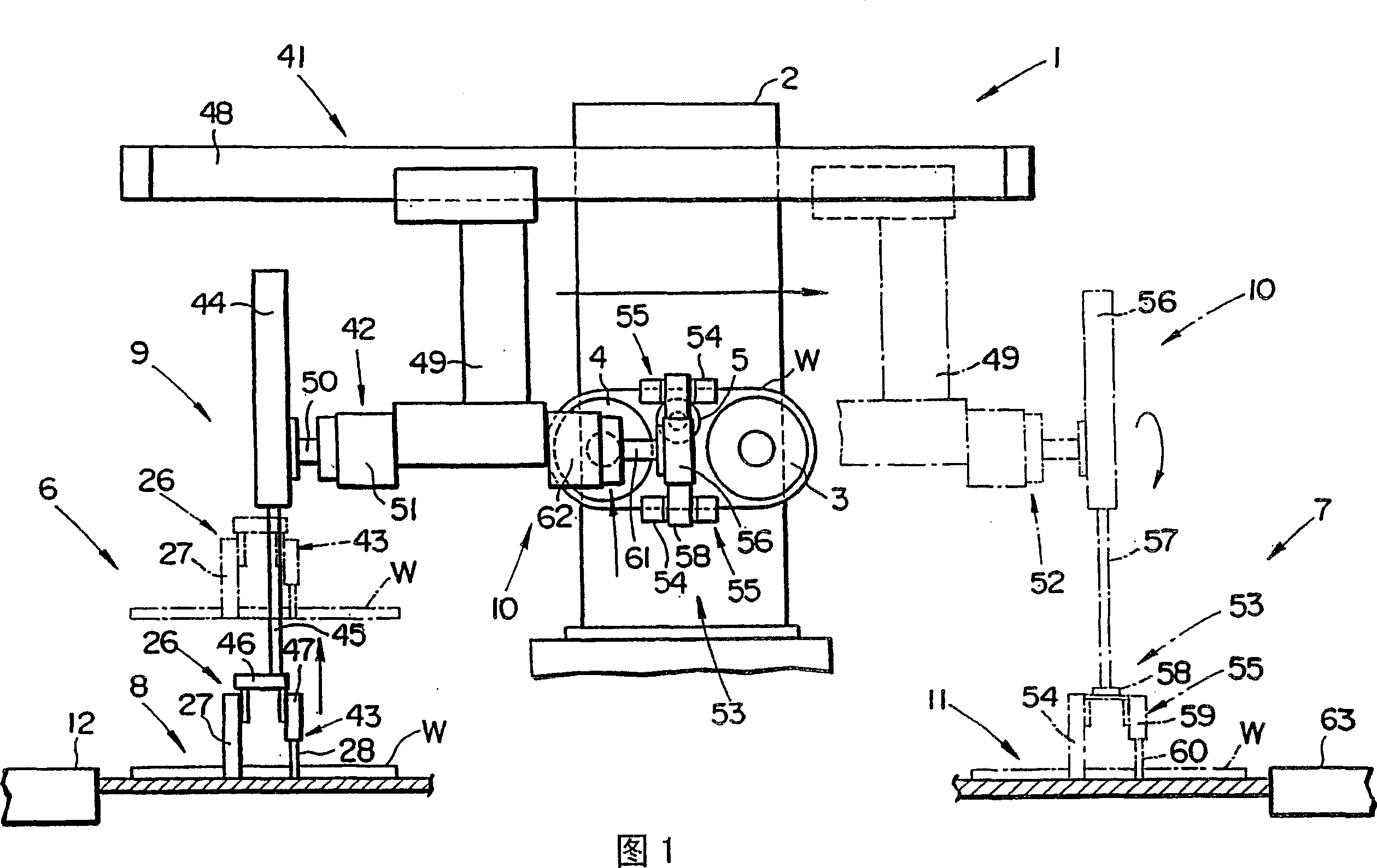
[0034] The loading and unloading device 1 of this embodiment, as shown in FIG. 1 , works while supporting the elastic endless belt-shaped metal ring W on the driving roller 3 and the driven roller 4 of the perimeter straightening machine 2. , the metal ring W supported on the driving roller 3 and the driven roller 4 is taken out. The perimeter straightening machine 2 has a straightening roller 5 that can be raised and lowered between the driving roller 3 and the driven roller 4, and the straightening roller 5 is raised by a lifting mechanism (not shown) to correct the circumference of the metal ring W. In addition, the driven roller 4 is moved in the horizontal direction by a roller moving mechanism (not shown) so as to be separated from the driving roller 3 when the circumference of the metal ring W is corrected, so that tension can be applied to the metal ring W.

[0035] Putting in and taking out device 1 is made of metal ring putting device 6 and metal ring taking out devi...


PUM


Abstract

A metal ring loading and unloading apparatus is capable of loading and unloading a metal ring quickly and highly accurately for increased efficiency. The metal ring loading and unloading apparatus has a moving unit (41) slidably movable along a rail (48) which extends from a loaded ring placement unit (8) to an unloaded ring placement unit (11). On the moving unit (41), there are mounted a loaded ring delivering unit (9) for holding and delivering a metal ring (W) on the loaded ring placement unit (8) and an unloaded ring delivering unit (10) for removing the metal ring (W) from support rollers (3, 4) and delivering the metal ring (W) to the unloaded ring placement unit (11). The loaded ring placement unit (8) has a pressing unit for radially pressing the metal ring (W) to deform the metal ring (W) into a substantially elliptical shape. The loaded ring delivering unit (9) has a loaded ring gripping unit (26) for gripping the metal ring (W) deformed by the pressing unit. The unloaded ring delivering unit (10) has an unloaded ring gripping unit (53) for gripping the metal ring (W) under its own recovering resiliency produced when the support rollers (3, 4) move toward each other. The unloaded ring placement unit (11) has a releasing unit for releasing the metal ring (W) from the unloaded ring gripping unit (53).

Description

[0001] This application is a divisional application, the international application number of the original application is PCT / JP01 / 08106, the application date is September 18, 2001, and the invention name is: metal ring insertion and removal device. technical field [0002] The invention relates to a metal ring putting in and taking out device for putting an elastic metal ring into and supporting it on a supporting roller, and taking out the metal ring supported on the supporting roller at the same time. Background technique [0003] For example, in a belt used to transmit power in a continuously variable transmission, a laminated ring in which a plurality of metal rings are laminated is used in order to integrate a plurality of elements stacked in a ring shape. The metal rings that make up this kind of laminated ring are formed by cutting a cylindrical roller into circular sheets at regular intervals to form endless belts, and then put them into a rolling machine or a perimet...

Claims


Application Information

Patent Timeline
Patent Type & Authority Patents(China)
IPC IPC(8): B21J15/08B21D53/14B21D43/00
Inventor 佐藤秀司成崎祐二冈野清则富泽实新田政雄渡部良晴
Owner HONDA MOTOR CO LTD
Features
  • R&D
  • Intellectual Property
  • Life Sciences
  • Materials
  • Tech Scout
  • Unparalleled Data Quality
  • Higher Quality Content
  • 60% Fewer Hallucinations
Learn More