Check patentability & draft patents in minutes with Patsnap Eureka AI!

Plasma display panel with pseudo-partition rib

A display panel, plasma technology, applied in alternating current plasma display panels, gas discharge tubes/containers, electrical components, etc., can solve the problems of uneven brightness and increased volume of discharge cells

Inactive Publication Date: 2004-05-12
SAMSUNG SDI CO LTD
View PDF1 Cites 4 Cited by
  • Summary
  • Abstract
  • Description
  • Claims
  • Application Information

AI Technical Summary

Problems solved by technology

This results in an increase in the volume of the discharge cells at the edge of the display area, thereby causing unevenness in luminance

Method used


Image

  • Plasma display panel with pseudo-partition rib
  • Plasma display panel with pseudo-partition rib
  • Plasma display panel with pseudo-partition rib

Examples


Embodiment Construction

[0025] Embodiments of the present invention will be described in detail below with reference to the accompanying drawings.

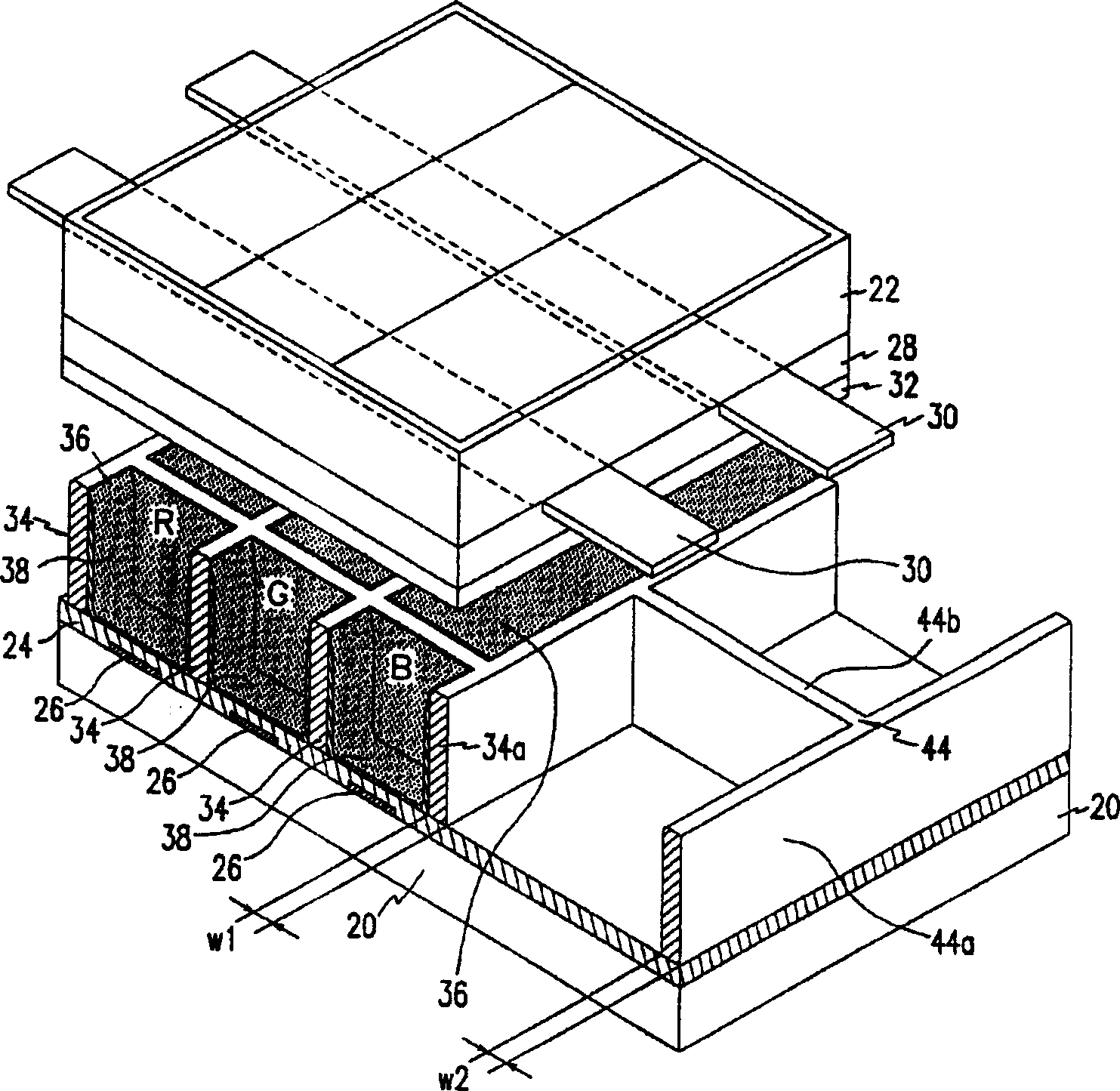
[0026] figure 1 is a partially exploded perspective view of a plasma display panel (PDP) according to an embodiment of the present invention, as figure 1 As shown, the plasma display panel includes a first substrate 20 and a second substrate 22 that are substantially parallel to each other with a certain distance between them, and a discharge structure is formed between the two substrates 20 and 22 . The display structure is used to complete the image display of the plasma display panel.

[0027] In this embodiment, the address electrodes 26 are formed on the surface of the first substrate 20 facing the second substrate 22 . The stripe-like pattern is formed by providing address electrodes 26 arranged in parallel and maintaining a predetermined interval. Also formed on the first substrate 20 is a first insulating layer 24 covering those address electr...


PUM


Abstract

A plasma display panel includes first and second substrates that are substantially parallel to each other with a predetermined gap therebetween. The substrates include a display region and a non-display region. Barrier ribs are mounted between the first and second substrates within the display region and define discharge cells. The barrier ribs include an outermost barrier rib located at an edge of the display region. Dummy barrier ribs are mounted between the first and second substrates within the non-display region. The dummy barrier ribs include a first sub barrier rib disposed at a predetermined distance from the outermost barrier rib, and at least one second sub barrier rib connected to the first sub barrier rib and the outermost barrier rib.

Description

technical field [0001] The present invention relates to a plasma display panel (PDP), especially a plasma display panel with dummy barrier ribs formed in a non-display area. Background technique [0002] As is well known, a plasma display panel (PDP), one of the most commonly used structures in the flat panel display field, is widely used in wall-mounted televisions and similar display fields. A predetermined image is displayed in a plasma display panel by using a discharge structure of discharge cells. [0003] The discharge cells are manufactured by forming ribs on a substrate according to a predetermined pattern (for example, a stripe pattern or a grid pattern). The ribs include real ribs in the display area (hereinafter referred to as "ribs" in corresponding places) and dummy ribs in the non-display area. [0004] In other words, by forming dummy barrier ribs in the non-display area on the periphery of the display area, each structural component of the plasma display p...

Claims


Application Information

Patent Timeline
Patent Type & Authority Applications(China)
IPC IPC(8): H01J11/12H01J11/14H01J11/22H01J11/24H01J11/26H01J11/34H01J11/36
CPCH01J11/36H01J11/12H01J2211/368
Inventor 金禹泰许银起
Owner SAMSUNG SDI CO LTD
Features
  • R&D
  • Intellectual Property
  • Life Sciences
  • Materials
  • Tech Scout
  • Unparalleled Data Quality
  • Higher Quality Content
  • 60% Fewer Hallucinations
Learn More