Cross slip-ring oil supply structure for vortex type compressor

A technology of scroll compressors and Oldham slip rings, applied in the field of scroll compressors, can solve the problems of reduced overall compressor efficiency, shortened compressor life, and wear, and achieve the effects of reducing wear and stabilizing rotary motion

Inactive Publication Date: 2005-01-19
LG ELECTRONICS (TIANJIN) APPLIANCES CO LTD
View PDF0 Cites 8 Cited by
  • Summary
  • Abstract
  • Description
  • Claims
  • Application Information

AI Technical Summary

Problems solved by technology

[0014] However, in the past scroll compressors, the oil scattered at the front end of the drive shaft (4) is filled in the shaft hole (1a) of the main frame (1), and then flows to the main frame (1) and the shaft hole (1a) of the main frame (1). The smooth part between the movable scroll (3) is supplied, and part of it is re-supplied between the Oldham slip ring (5) and the main frame (1), but according to the smoothness between the main frame (1) and the movable scroll (3) The supply amount of oil caused by the contact of the Oldham slip ring (5) and the main frame (1) is insufficient, and cannot be supplied to the smooth part between the Oldham slip ring (5) and the main frame (1), so the first anti-rotation protrusion (5a) of the Oldham slip ring (5) The anti-rotation groove (1c) of the combined main frame (1) will produce wear and tear, which will have a bad influence on the rotating motion of the movable scroll (3), not only the overall efficiency of the compressor will decrease but also there will be problems caused by the Oldham slip ring (5 ) The damage caused by shortening the life of the compressor

Method used


Image

  • Cross slip-ring oil supply structure for vortex type compressor
  • Cross slip-ring oil supply structure for vortex type compressor
  • Cross slip-ring oil supply structure for vortex type compressor

Examples


Embodiment Construction

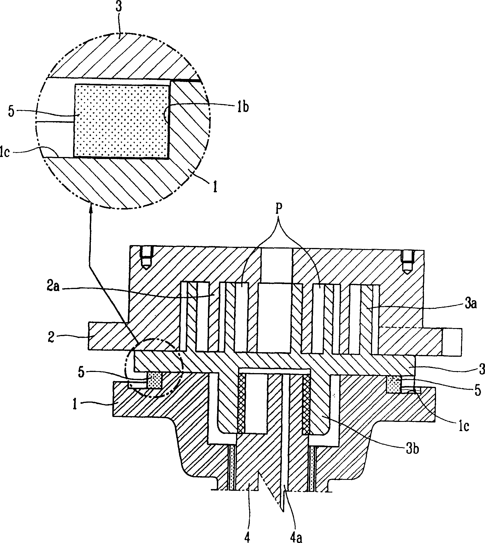
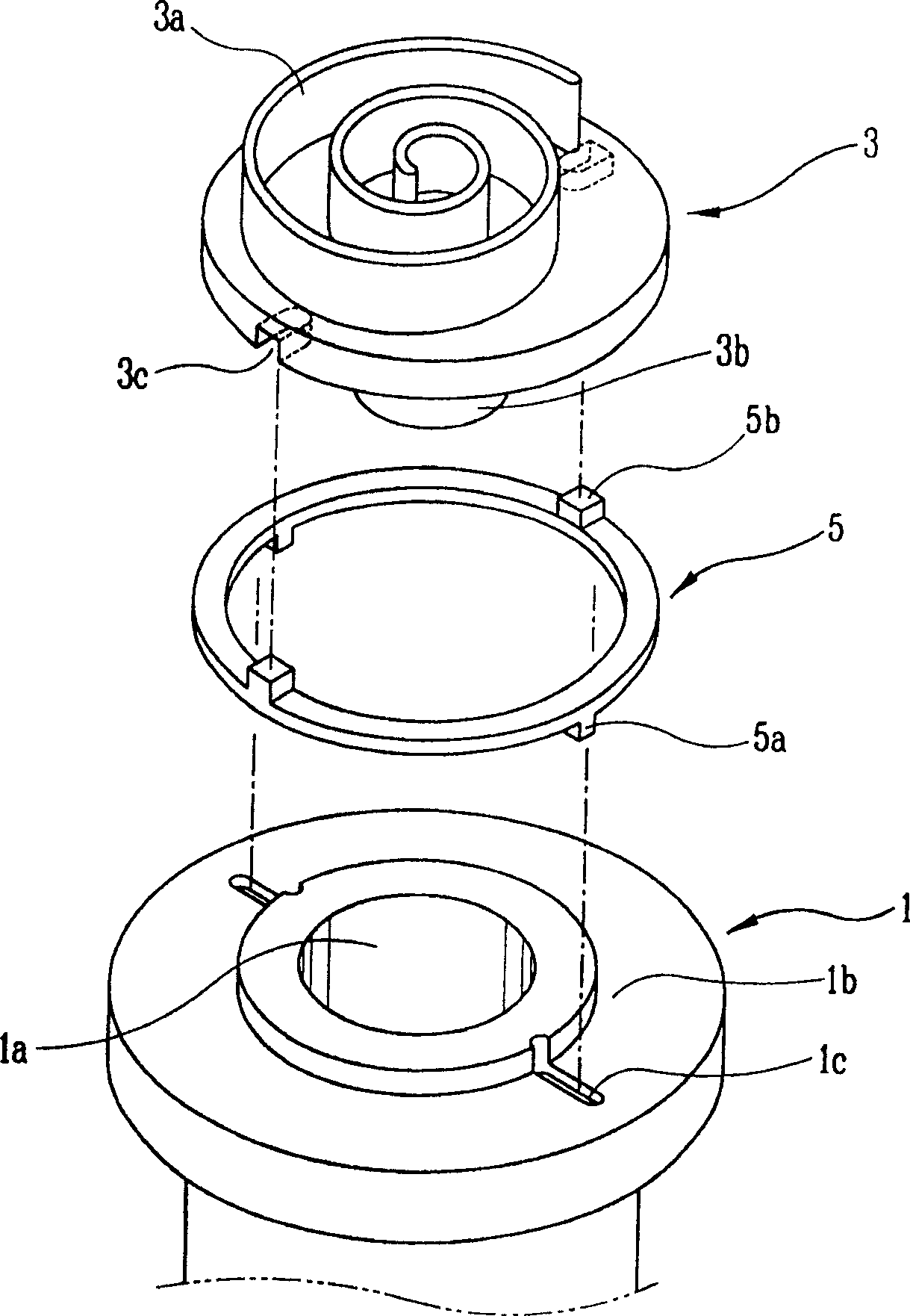
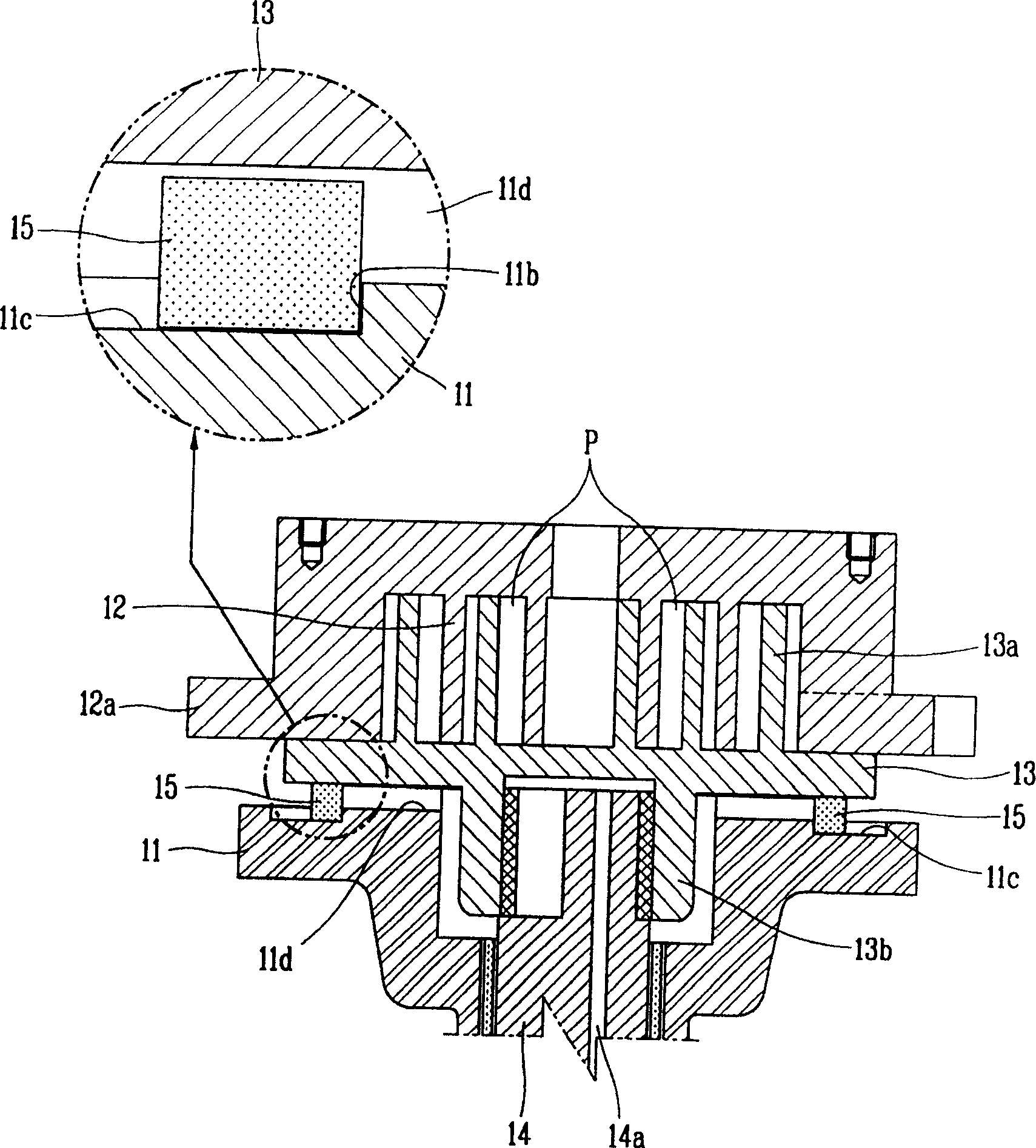
[0030] image 3 is a schematic partial longitudinal section of a scroll compressor according to the present invention, Figure 4 It is an exploded perspective view of the compression mechanism part of the scroll compressor of the present invention, Figure 5 It is a schematic diagram for explaining the state of supplying oil to the Oldham ring in the scroll compressor according to the present invention.

[0031] As shown in the figure, according to the formation of the scroll compressor of the present invention, it comprises: a main frame (11) fixed in a sealed container with a certain amount of oil; a fixed scroll (11) fixed in the main frame (11) 12); In order to engage with the scroll of the fixed scroll (12), a spiral scroll is formed and a movable scroll (13) with a plurality of compression chambers (P) capable of continuous movement is formed; the movable scroll (13) ) connecting portion (13b) eccentrically combined drive shaft (14); an Oldham slip ring ( 15) and so o...


PUM


Abstract

The invention is about a cross slip ring oil supply structure of scroll compressor, which comprises: a main frame fixed in the sealed container filled with some oil; a static scroll disk fixed in the main frame; a screw scroll formed for gearing with the scroll of the static scroll disk, a dynamic scroll disk, joined in the frame for rotary motion and for forming a compressing chambers capable of continuously moving together; a driving shaft combined in the dynamic scroll disk, capable of transferring the driving force of the motor, and supply the oil in the sealed container to the smooth part; and a cross slid ring between the frame and the dynamic scroll disk for preventing self-rotation of the dynamic scroll disk and guiding the rotary motion. The invention prevents the abrasion between the main frame and cross slid ring.

Description

technical field [0001] The invention belongs to a scroll compressor, in particular to an oil supply structure of an Oldham compressor for lubricating by directly supplying oil between the Oldham and a main frame. Background technique [0002] Generally speaking, the scroll compressor is widely used in the field of air conditioners. As a high-efficiency and low-noise compressor, its operation method is to make the two turbines rotate relative to each other, and through this, the turbines The multiple compression chambers in between are formed in pairs, and the compression chambers move rapidly toward the center, and at the same time, the volume becomes smaller, so that the refrigerant gas is continuously inhaled, compressed and discharged. [0003] In order to make the two turbines perform relative rotary motion, an anti-rotation device called an Oldham slip ring is inserted between the movable scroll and the frame supporting the turbine, and the rotating turbine is forced to...

Claims


Application Information

Patent Timeline
Patent Type & Authority Applications(China)
IPC IPC(8): F04C18/02F04C29/02
Inventor 裵埈晟
Owner LG ELECTRONICS (TIANJIN) APPLIANCES CO LTD
Why Eureka
Try Eureka