Refrigerating equipment

A refrigeration device and refrigerant technology, which is used in household refrigeration devices, cooling fluid circulation devices, refrigerators, etc., to achieve the effect of inhibiting the diffusion of abnormal sounds to the outside

Inactive Publication Date: 2005-07-20
DAIKIN IND LTD
View PDF1 Cites 2 Cited by
  • Summary
  • Abstract
  • Description
  • Claims
  • Application Information

AI Technical Summary

Problems solved by technology

[0005] As mentioned above, the conventional refrigerating apparatus has the problem of generating abnormal noise due to the gas refrigerant being injected into the suction pipe to mix the gas refrigerant.
And this problem does not only occur during the oil return operation, but also when gas is injected for other purposes, because the gas refrigerant is also injected into the suction side of the compressor, so there is the same problem

Method used


Image

  • Refrigerating equipment
  • Refrigerating equipment
  • Refrigerating equipment

Examples


Embodiment -

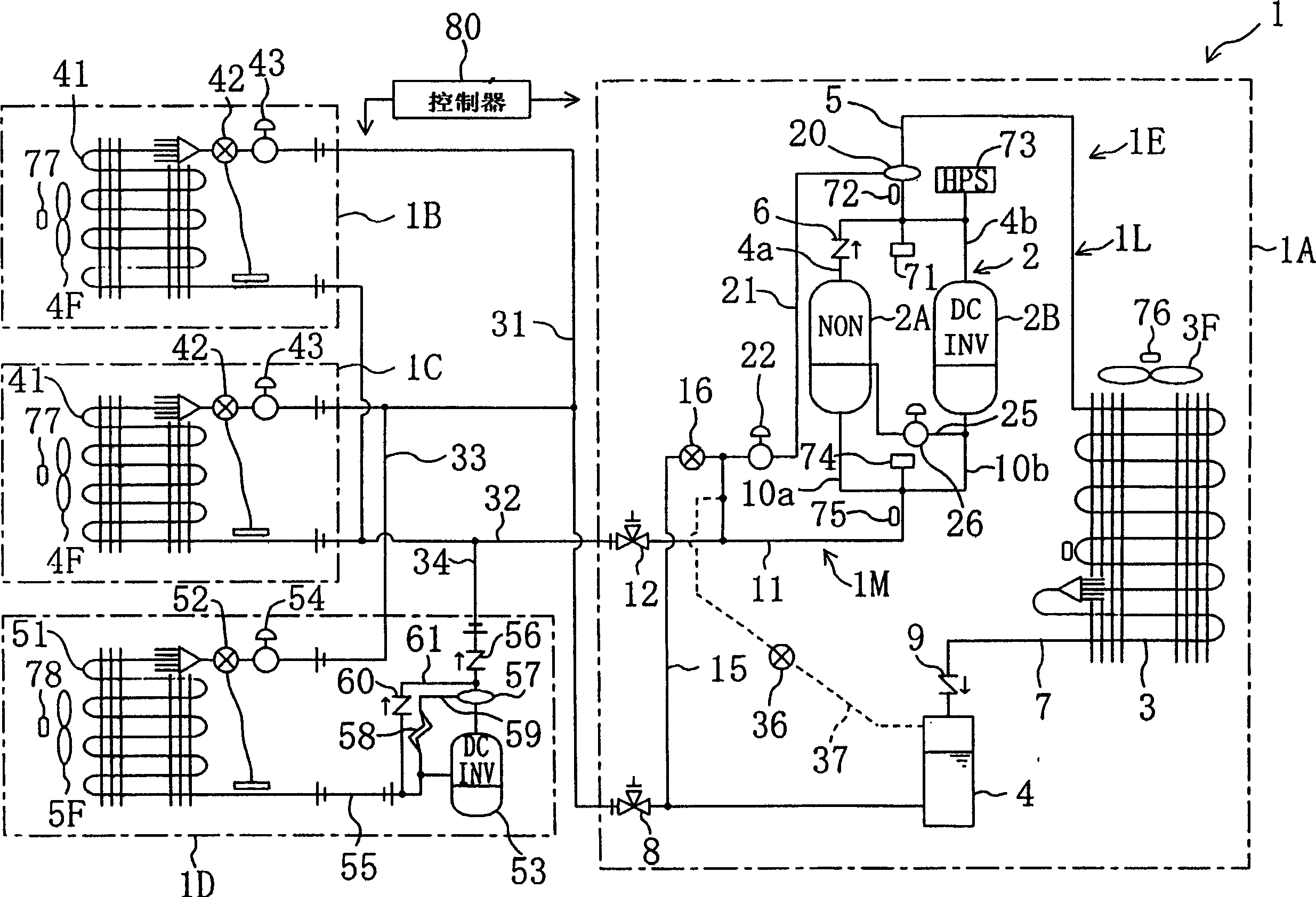
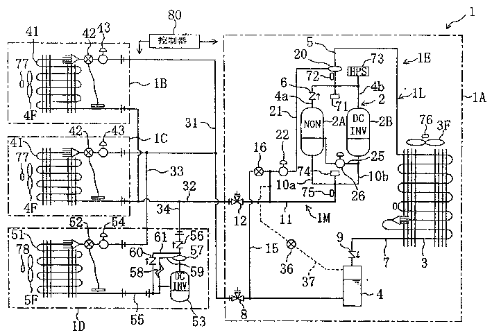
[0073] In the above-mentioned embodiments, the example in which the oil return passage 21 is connected to the liquid injection passage 15 has been described. In the present invention, on the premise that the mixing of gas and refrigerant does not occur substantially on the suction side of the compression mechanism 2, by The gas refrigerant is injected into the liquid refrigerant to suppress the occurrence of abnormal noise.

[0074] Therefore, the present invention is not limited to oil return, but is also applicable to a device having a gas injection passage for injecting gas refrigerant into a compressor. For example, in the loop structure of the above-mentioned embodiment, such as figure 1 As shown by the middle dotted line, the gas injection passage 37 provided with the flow rate adjustment valve 36 may be connected to the liquid injection passage 15 from the upper end of the gas tank 4 . The gas injection passage 37 can be used as a suction passage when the gas storage t...


PUM


Abstract

Refrigerating equipment so formed that gas refrigerant is filled into the suction tubes (10a, 10b) of compressors (2A, 2B) through an oil return passage (21) and a gas injection passage, comprising a liquid injection passage (15) for filling liquid refrigerant to the suction sides of the compressors (2A, 2B), wherein the oil return passage (21) and gas injection passage are connected to the liquid injection passage (15), whereby abnormal noise caused by the mixing of gas refrigerant in the suction tubes (10a, 10b) can be prevented.

Description

technical field [0001] The present invention relates to refrigerating equipment, and more particularly to measures for reducing the noise generated on the suction side of a compressor due to oil return, gas injection, and the like. Background technique [0002] Conventionally, there is a refrigerating apparatus that performs a vapor compression refrigerating cycle. The refrigerating apparatus is mainly used as a cooler of an air conditioner for cooling and heating a room, and is widely used as a cooler of a refrigerator, a freezer, and the like for storing food and the like. This refrigerating apparatus performs a vapor compression refrigerating cycle by sequentially passing refrigerant discharged from a compressor through a condenser, an expansion mechanism, and an evaporator. [0003] In this refrigerant circuit, the refrigerant discharged from the compressor contains refrigerating machine oil for lubricating the inside of the compressor. In order to return the refrigera...

Claims


Application Information

Patent Timeline
Patent Type & Authority Applications(China)
IPC IPC(8): F25B31/00
CPCF25D2700/12Y02B30/741F25B31/004F25B2700/21152F25B2700/21151F25B2700/1933F25B2500/12F25B2700/1931F25B2600/021F25B2400/22F25B2400/16F25B2400/075F25B2400/0751Y02B30/70
Inventor 竹上雅章谷本宪治
Owner DAIKIN IND LTD
Why Eureka
Try Eureka