

Clinching method and tool therefor
A tool and riveting technology, which is applied in the field of tools to realize the method, can solve problems such as the influence of the rheological process, the skew of the guide rod, and uncontrollable problems, and achieve the effect of easy control, high density, and high hardness
- Summary
- Abstract
- Description
- Claims
- Application Information
AI Technical Summary
Problems solved by technology
Method used
Image

Examples
Embodiment Construction
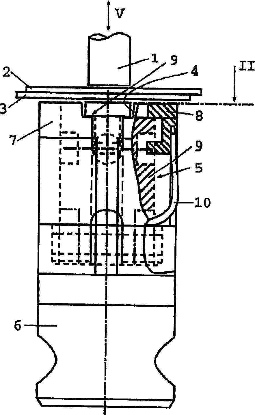
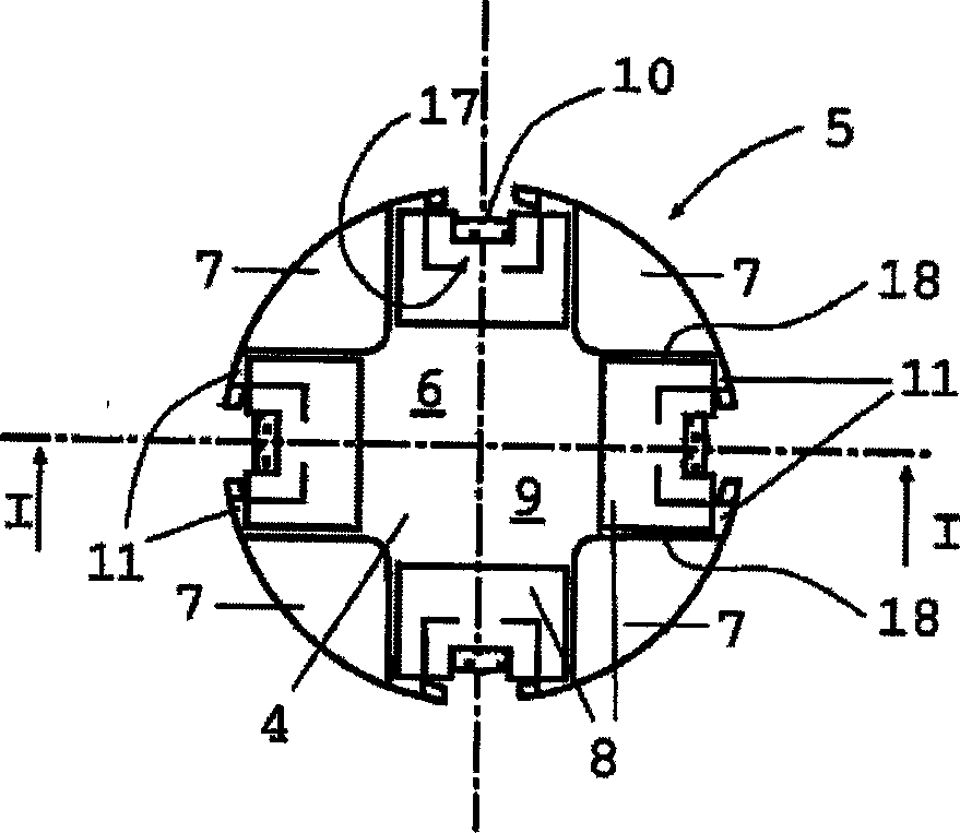
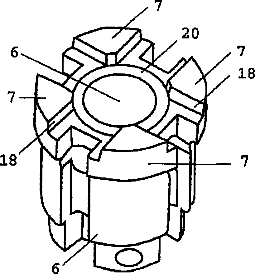
[0032] figure 1 and 2 A tool according to the invention is given in , in which the known machine tool is not used for riveting the sheet metal and for connecting the sheet metal with bolts, nuts etc., in particular the sheet metal is not perforated, but instead deep drawn, Causes significant distortion of deep-drawn material.
[0033] This tool is, on the one hand, a machine-driven plunger 1 which is placed on top of the two metal sheets 2 and 3 to be joined, opposite the working hole 4 of the multi-component mold 5 . The plunger 1 and the mold 5 are placed in the machine tool during use, wherein, for riveting, the plunger 1 is pressed down after the metal plates 2 and 3 have been placed. During the working stroke pointing downwards, the metal sheets 2 and 3 are first deep-drawn into the working hole 4 and then flow radially outwards on the bottom surface 9 of the working hole 4 as the driving force of the plunger 1 increases. , wherein the extruded material is first deep-d...
PUM
 Abstract
Description
Claims
Application Information