Flow measurer
A flow measuring device and flow technology, applied in the direction of measuring device, measuring flow/mass flow, liquid/fluid solid measurement, etc.
- Summary
- Abstract
- Description
- Claims
- Application Information
AI Technical Summary
Problems solved by technology
Method used
Image

Examples
example 1
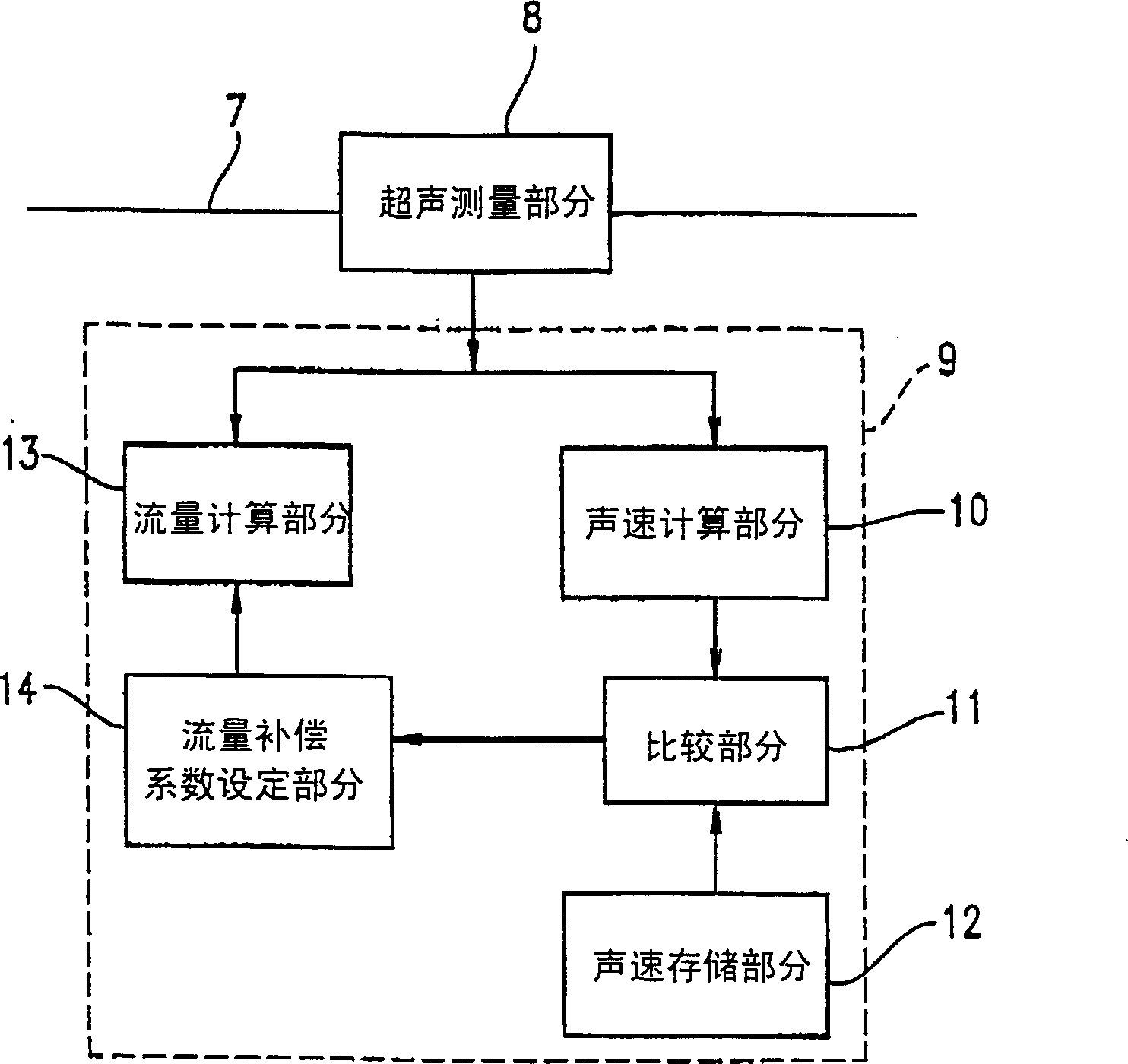
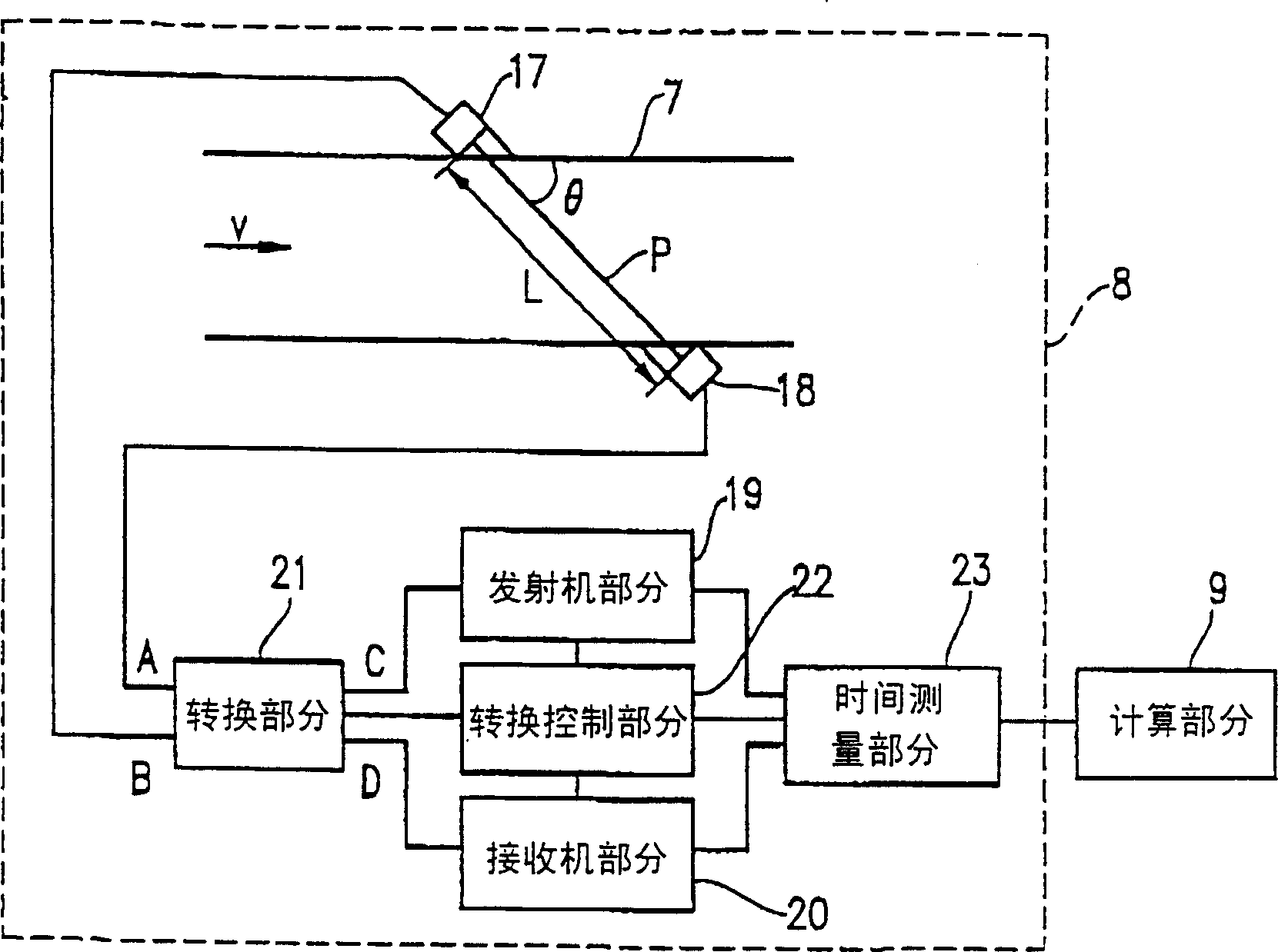
[0046] figure 2 The structure of the gas type identification system according to Example 1 of the present invention is shown. Such as figure 2As shown, the gas type identification system includes a flow path 7 , an ultrasonic measurement section 8 disposed in the flow path 7 , and a calculation section 9 for performing arithmetic operations on signals output from the ultrasonic measurement section 8 .
[0047] The calculation section 9 includes a sound velocity calculation section 10 , a comparison section 11 , a sound velocity storage section 12 , a flow calculation section 13 and a flow compensation coefficient setting section 14 .
[0048] Next, the operation and function of the gas type identification system will be described.
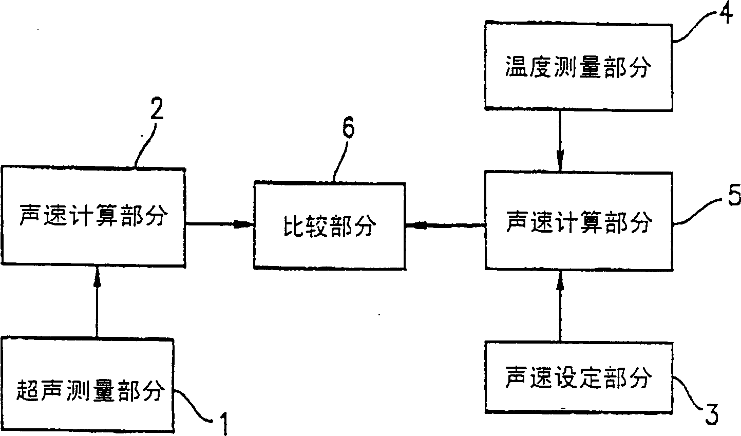
[0049] The sound velocity calculation section 10 calculates the sound velocity from the signal output from the ultrasonic measurement section 8 . The comparison section 11 compares the sound velocity calculated by the sound velocity calculatio...
example 2
[0082] Figure 7 The structure of the gas type identification system according to Example 2 of the present invention is shown.
[0083] Such as Figure 7 As shown, the gas type identification system includes a flow path 7, an ultrasonic measurement part 8 arranged in the flow path 7, and a calculation part 9 for performing arithmetic operations on signals output from the ultrasonic measurement part 8, arranged in the A dual mode valve 32 in the flow path 7, and a control section 33 for controlling the dual mode valve 32. The dual mode valve 32 is arranged downstream of the ultrasonic measuring portion 8 in the flow path 7 .
[0084] Apart from figure 2 In addition to the structure shown in , the calculating section 9 also includes an abnormality determining section 34 . The abnormality determination section 34 determines whether an abnormal gas is flowing through the flow path 7 . For example, if the type of gas expected to flow through the flow path 7 (i.e., gas type A)...
example 3
[0096] Figure 9 The structure of the gas type identification system according to Example 3 of the present invention is shown.
[0097] Such as Figure 9 As shown, the gas type identification system includes a flow path 7, an ultrasonic measurement part 8 arranged in the flow path 7, and a calculation part 9 for performing arithmetic operations on signals output from the ultrasonic measurement part 8, arranged in the A dual mode valve 32 in the flow path 7, and a control section 33 for controlling the dual mode valve 32. The dual mode valve 32 is arranged downstream of the ultrasonic measuring portion 8 in the flow path 7 .
[0098] Apart from figure 2 In addition to the structure shown in , the calculating section 9 also includes a security standard setting section 43 and an abnormality determining section 44 .
[0099] In Example 3, the same constituent elements as in Example 1 are denoted by the same reference numerals, and their descriptions are omitted.
[0100] F...
PUM
 Abstract
Description
Claims
Application Information
 - R&D
- Intellectual Property
- Life Sciences
- Materials
- Tech Scout
- Unparalleled Data Quality
- Higher Quality Content
- 60% Fewer Hallucinations
Browse by: Latest US Patents, China's latest patents, Technical Efficacy Thesaurus, Application Domain, Technology Topic, Popular Technical Reports.
© 2025 PatSnap. All rights reserved.Legal|Privacy policy|Modern Slavery Act Transparency Statement|Sitemap|About US| Contact US: help@patsnap.com