

Cartridge and image forming apparatus
A technology for imaging equipment and process cartridges, applied in the fields of process cartridges and imaging devices, can solve problems such as the inability to prevent toner leakage
- Summary
- Abstract
- Description
- Claims
- Application Information
AI Technical Summary
Problems solved by technology
Method used
Image

Examples
Embodiment Construction
[0037] example
[0038] will refer to Figures 1 to 12 Some aspects of the invention are described.
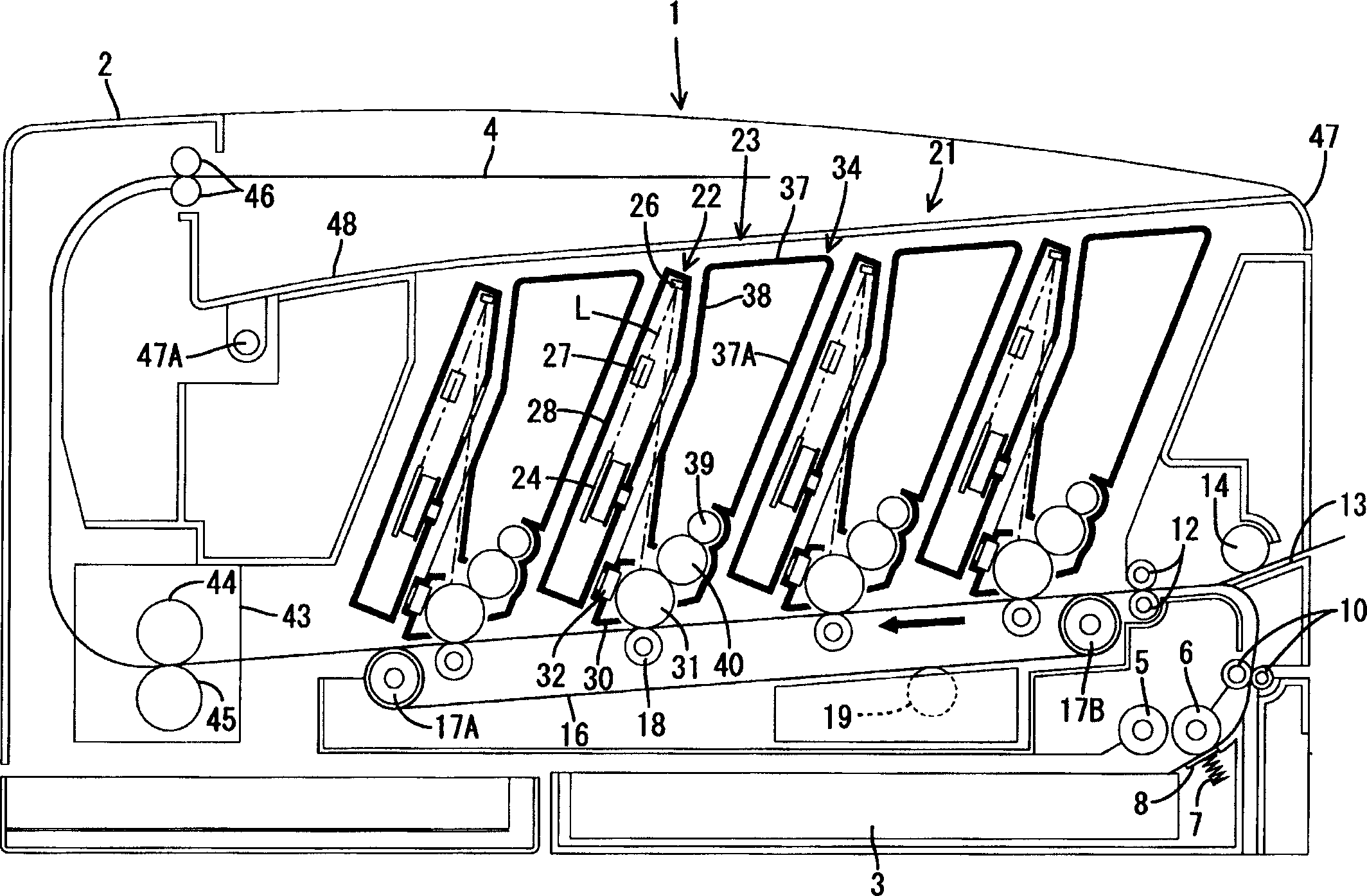
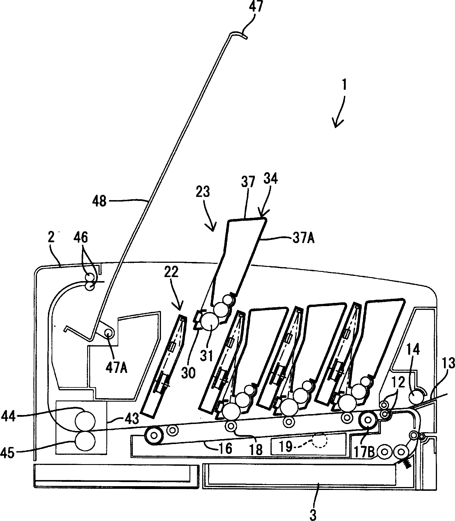
[0039] figure 1 is a side sectional view of the overall structure of a laser printer 1 as an image forming apparatus according to aspects of the present invention. The laser printer 1 is a direct tandem color laser printer having four photosensitive drums 31 corresponding to black, cyan, magenta, and yellow, respectively. In the description below, figure 1 The right side in is called the front side.
[0040] The laser printer 1 includes a lower paper feed tray 3 inside a main body case 2 . A paper feed tray 3 is detachably attached to the main body case 2 from the front side. The paper feed tray 3 is configured to supply a stack of paper 4 for image formation. A platen (not shown) is provided at the bottom of the paper feed tray 3 and is configured to lift the leading end of the paper 4 . The pick-up roller 5 and the paper supply roller 6 arranged in series, and the pa...
PUM
 Abstract
Description
Claims
Application Information