Puzzle lock and its mechanism

A combination lock and lock tongue technology, applied in the field of electronic combination locks and their mechanisms, can solve problems such as difficult to save power, and achieve the effect of reliable locking reset, simple structure, and close electromechanical integration

Inactive Publication Date: 2011-09-07
SHANGHAI BUDDY TECHONOLOGICAL
View PDF6 Cites 0 Cited by
  • Summary
  • Abstract
  • Description
  • Claims
  • Application Information

AI Technical Summary

Problems solved by technology

[0006] Although the above technical solution also realizes the hook-shaped plate from the disengaged position from the cam to the position where the hook part is engaged with the cam groove, the whole process is driven by a motor, so it is difficult to save power

Method used


Image

  • Puzzle lock and its mechanism
  • Puzzle lock and its mechanism
  • Puzzle lock and its mechanism

Examples


Embodiment Construction

[0034] The present invention will be further described below in conjunction with preferred embodiments.

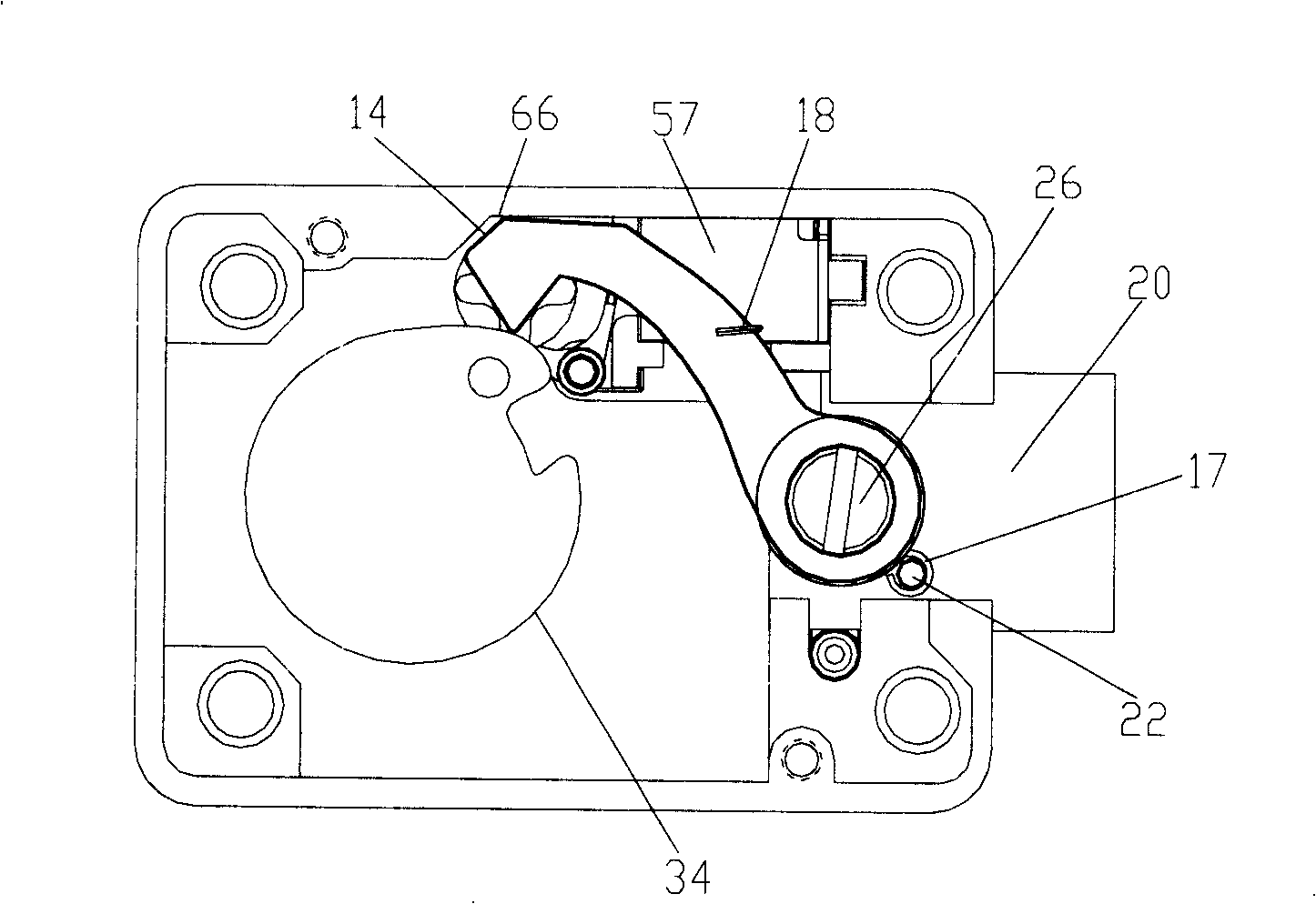
[0035] Such as figure 1 with Figure 4 As shown, the hook-shaped plate 10 is hook-shaped, and the root is ring-shaped, and is hingedly fixed on the dead bolt 20 by a screw 26. The bias spring 16 is sleeved on the screw 26, and one end is fixed on the post 22, and the other end is hooked on the hook. On the shaped plate 10, the hook shaped plate 10 has a tendency to rotate counterclockwise.

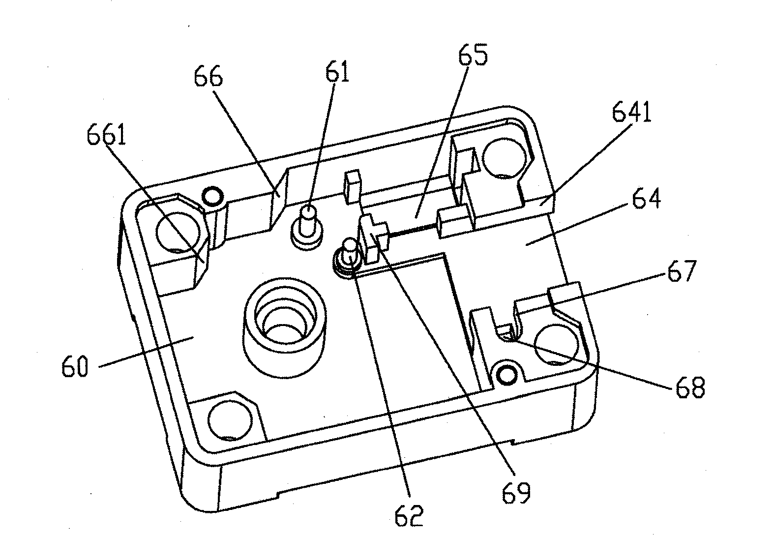
[0036] figure 1 with image 3 Shows the state where the hook plate 10 is locked, wherein the pawl lever 50 is shaped like Figure 8 As shown, it is sleeved on the shaft post 62 located in the lock box, and is slidably fitted. One end 56 of the bias spring 59 is fixed on the protrusion 69 in the lock box, and the other end 55 is hooked on the second claw wall of the claw lever 50 At 54, the claw lever 50 has a tendency to rotate clockwise, so that the second end 53 of the claw leve...


PUM


Abstract

A passwords lock and the mechanism comprise unciform board, cam, and fixed equipment. The first end of unciform board is hinged with bolt and the second end is set on the position contacting or disengaging with cam face. At contacting position, cam is rotated to prefabricated angle and the second end of unciform board is locked with the groove on cam surface. Cam is connected with hand or knob spindle. After locked with the second end of unciform board, cam can drive bolt retract from closed lock position to opened lock position and vice versa. Unciform board is fixed to disengaging position of said cam surface by fixed equipment. After authorization signal is received, the locking is released and unciform board is pressed to contacting position of said cam. When unciform board is locked with the groove on cam surface again it can be push to said disengaging position by rotating cam. Here unciform board is locked to the disengaging position by fixed equipment again.

Description

technical field [0001] The invention relates to a combination lock and its mechanism, more specifically, to an electronic combination lock and its mechanism. Background technique [0002] The relatively power-saving electronic combination lock mechanism usually uses an electronically controlled clutch or electronically controlled release to control the combination of the lock handle or knob with the deadbolt or bolt to realize the unlocking and locking functions. [0003] Patent US5307656 discloses a combination lock and its mechanism. The hook plate of the lock mechanism is disengaged from the cam when the dead bolt is in the extended position. When the lock is unlocked, the electromagnet attracts and causes a steel ball set on its moving part to move upwards into the wall hole of the casing, and makes the steel ball contact with a protruding point on the cam surface. At this time, turning the cam can push the steel ball and the casing. The tubes move parallel together, on...

Claims


Application Information

Patent Timeline
Patent Type & Authority Patents(China)
IPC IPC(8): E05B3/00E05B49/00E05B47/00
Inventor 袁梦笑
Owner SHANGHAI BUDDY TECHONOLOGICAL
Why Eureka
Try Eureka