Automobile control system

A hydraulic control valve and hydraulic braking technology, which is applied in the field of automobile control systems, can solve the problems of difficult control of braking amplitude, single control function, and difficult integration, etc. Effect

Active Publication Date: 2013-03-20
BYD CO LTD
View PDF5 Cites 0 Cited by
  • Summary
  • Abstract
  • Description
  • Claims
  • Application Information

AI Technical Summary

Problems solved by technology

[0007] The purpose of the present invention is to overcome the defects of large friction, difficult to control the braking range, difficult to integrate, and single control function in the prior art, and provide a control mechanism with small friction, easy to control, easy to integrate, and capable of multiple control functions. car control system

Method used


Image

  • Automobile control system
  • Automobile control system
  • Automobile control system

Examples


Embodiment Construction

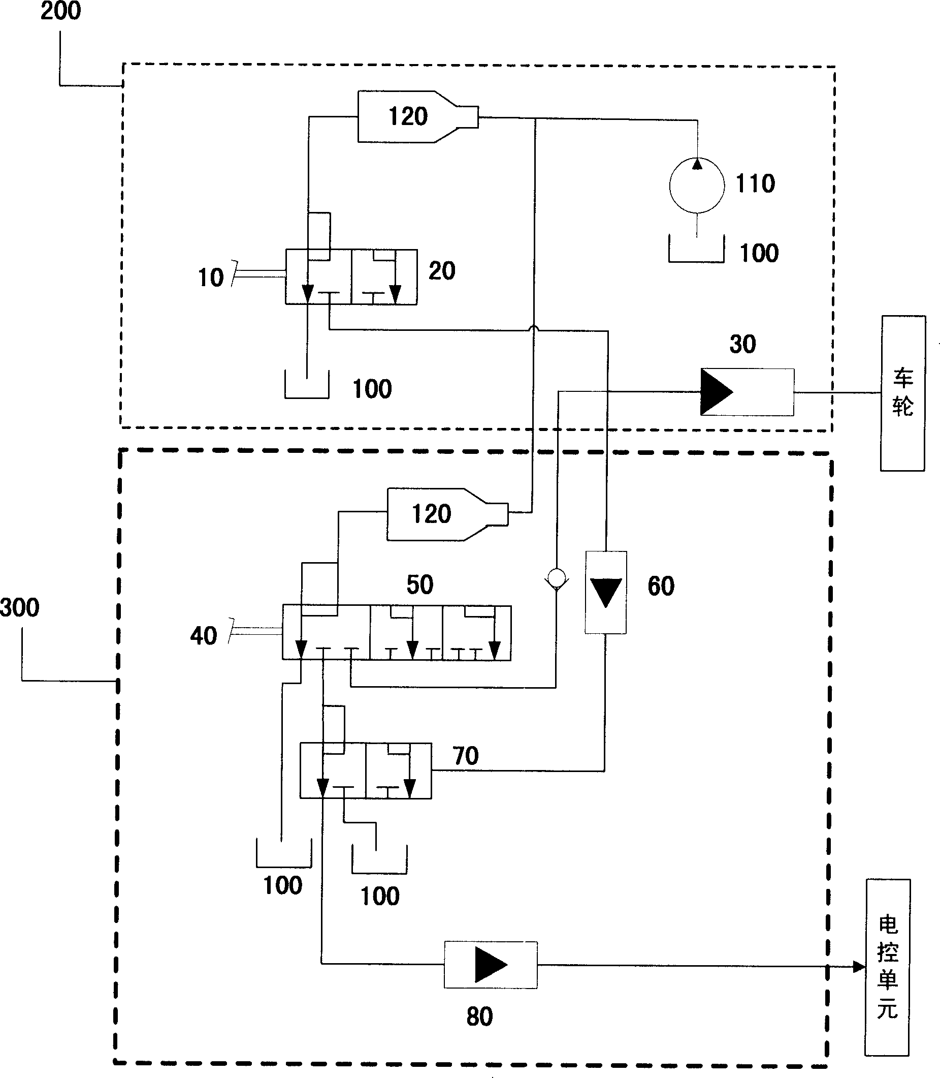
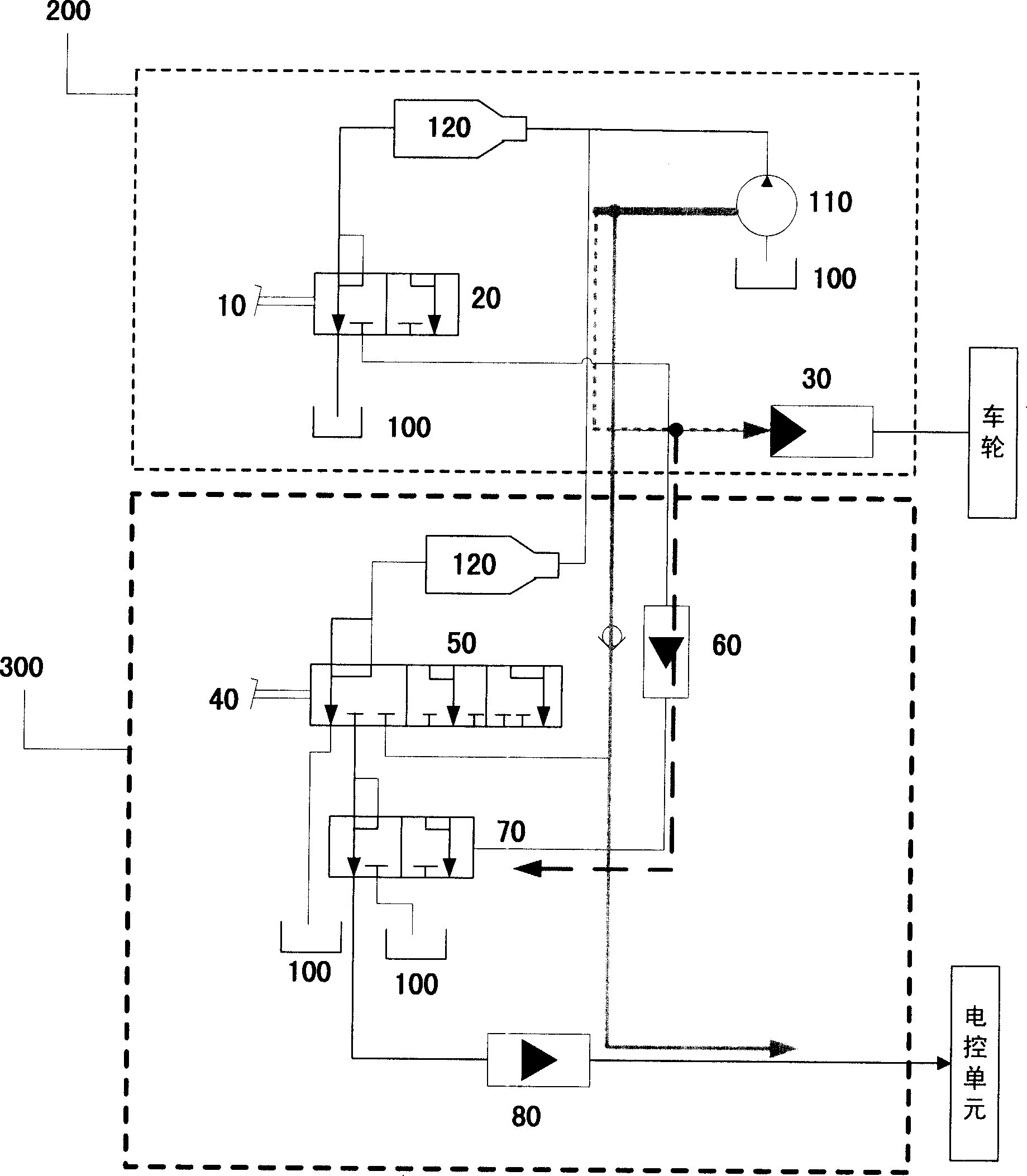
[0015] figure 2 A schematic diagram showing a vehicle control system according to the present invention. The vehicle control system includes a hydraulic acceleration unit 300 and a hydraulic braking unit 200, wherein the hydraulic acceleration unit 300 includes an accelerator pedal 40, a hydraulic control valve 50, a brake hydraulic pressure sensor 60, a solenoid valve 70, and an acceleration hydraulic pressure sensor 80, wherein the accelerator pedal 40 is mechanically connected to the spool of the hydraulic control valve, the first output position of the hydraulic control valve is connected to the hydraulic oil tank 100, the second output position of the hydraulic control valve is connected to the input position of the solenoid valve 70, and the hydraulic control valve The third output position of the solenoid valve 70 is connected to the inlet of the brake wheel cylinder 30 of the hydraulic brake unit 200, the first output position of the solenoid valve 70 is connected to ...


PUM


Abstract

The automatic misoperation preventing control system includes one hydraulic acceleration unit and one hydraulic braking unit. The hydraulic acceleration unit includes one accelerating pedal, one hydraulic control valve, one braking hydraulic sensor, one solenoid valve and one accelerating hydraulic sensor. The accelerating pedal is connected mechanically with the valve core of the hydraulic control valve; the hydraulic control valve has one first output connected to the hydraulic oil tank, one second output connected to the input of the solenoid valve and one third output connected to the braking cylinder inlet of the hydraulic control valve; the solenoid valve has one first output connected to the accelerating hydraulic sensor and one second output connected the hydraulic oil tank; and the braking hydraulic sensor is connected to the braking cylinder inlet of the hydraulic braking unit.

Description

technical field [0001] This invention relates to automotive control systems. Background technique [0002] With the development of my country's automobile industry, automobiles are becoming increasingly popular. In the middle of driving, accidents of personal injury and death caused by misoperation during emergency braking by car drivers occur from time to time. [0003] In the prior art, mechanical structures such as mechanical pedals, gears, and overrunning clutches are used to compensate for the mishandling of the accelerator during emergency braking, so as to achieve safe driving and stable handling. [0004] figure 1 Shown is a vehicle control device in the prior art. It includes an accelerator pedal 1, a pedal rod 3, the pedal rod 3 is fixedly connected to the accelerator shaft 2, and meshing gears 4 and 5 are arranged between the accelerator shaft 2 and another shaft 10, and the other shaft 10 is connected to the connecting block 6 through a clutch 7, and the conne...

Claims


Application Information

Patent Timeline
Patent Type & Authority Patents(China)
IPC IPC(8): B60W10/06B60W10/18B60W30/08B60W10/188B60W30/00
Inventor 陈伟
Owner BYD CO LTD
Why Eureka
Try Eureka