

Device for capturing wave energy
a technology of wave energy and device, applied in the direction of machine/engine, machine components, sea energy generation, etc., can solve the problems of reducing the performance of devices and reducing the performance of the devices
- Summary
- Abstract
- Description
- Claims
- Application Information
AI Technical Summary
Benefits of technology
Problems solved by technology
Method used
Image

Examples
Embodiment Construction
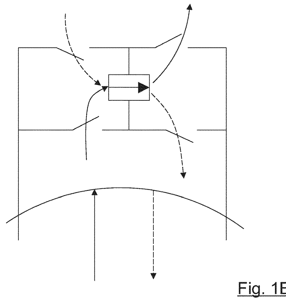
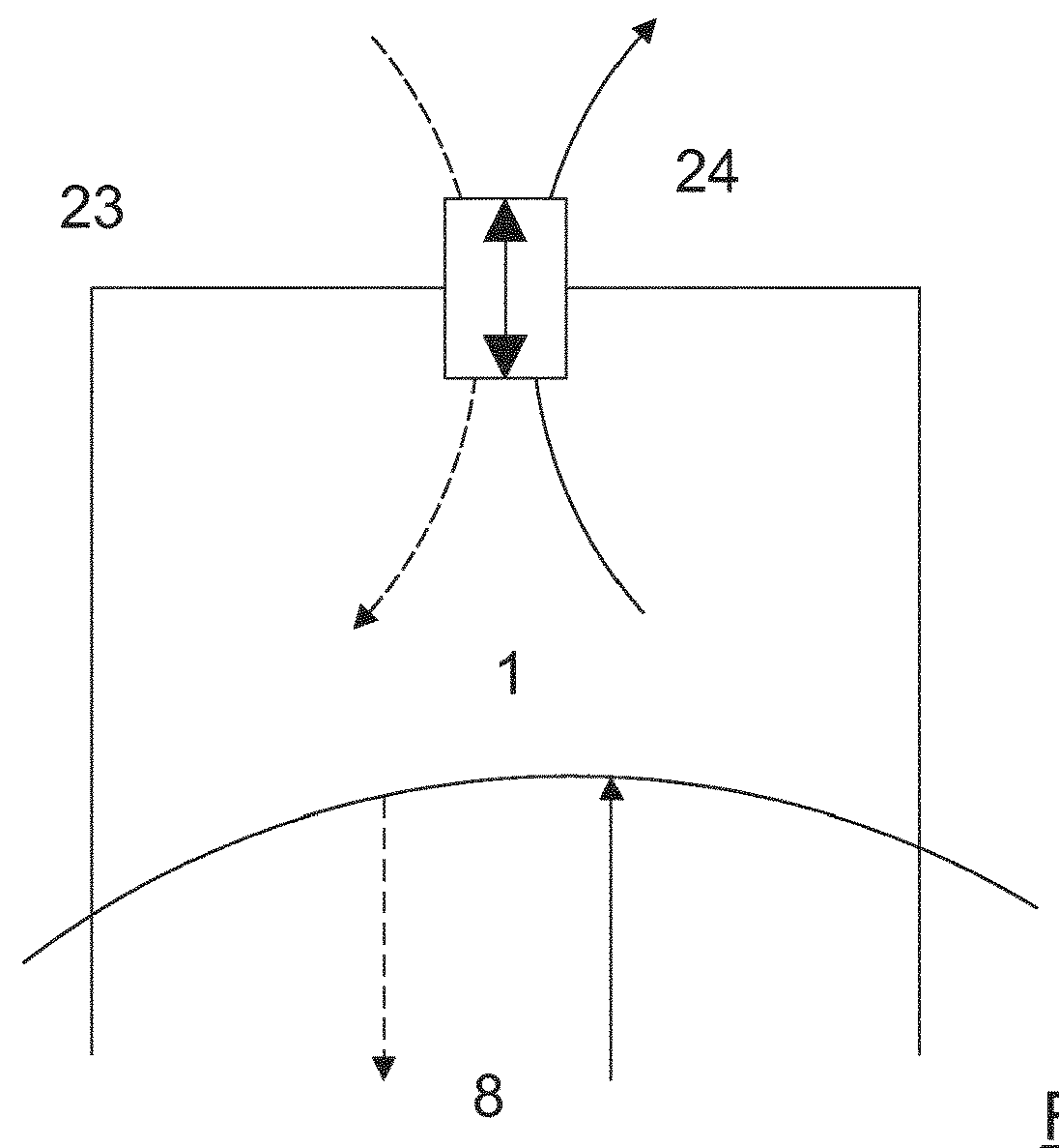
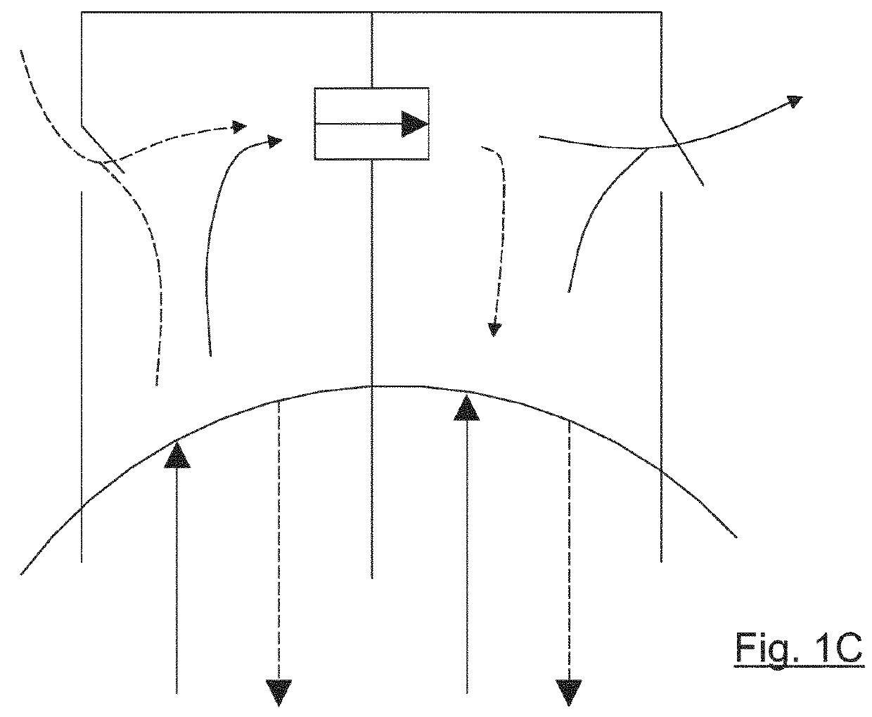
[0021]The invention relates to a device for generating energy from waves by means of the OWC technique, wherein the pressure and vacuum accumulators, the air chambers and the water columns are integrated into the same structure, without connecting piping between them, thus preventing loss of pressure.
[0022]Another subject matter of the invention is for the pressure and vacuum accumulators to each have their own unidirectional turbine directed towards the atmosphere, instead of a single turbine between the two accumulators. To this is added the characteristic that the chambers be in contact with the atmosphere, instead of chambers connected to one another, as there is a turbine working between two closed volumes of a limited size, and the flow to be sent through the turbine is smaller and the turbulence higher, causing a reduction in performance. The turbines need stability, and this stability is provided by the pressure and vacuum accumulators, each of which is associated to its own...
PUM
 Abstract
Description
Claims
Application Information