Board-connecting electric connector device

a technology of electric connectors and connector devices, which is applied in the direction of coupling devices, coupling bases/cases, electrical devices, etc., can solve the problems of insufficient electromagnetic shielding function and easy generation of comparatively large gaps, and achieve efficient blocking, sufficient emi measures, and simple configuration

Active Publication Date: 2018-09-25
DAIICHI SEIKO CO LTD
View PDF36 Cites 12 Cited by
  • Summary
  • Abstract
  • Description
  • Claims
  • Application Information

AI Technical Summary

Benefits of technology

[0009]Therefore, it is an object of the present invention to provide a board-connecting electric connector device configured to enable, by a simple configuration, sufficient electromagnetic shielding about both of electric connectors, which are in a mutually mated state.
[0011]According to the present invention provided with such a configuration, the electromagnetic shielding functions with respect to the contact connecting portions are obtained in each of the first and second electric connectors by the respective shield wall portions; and, when the first and second electric connectors are mated with each other, the shield wall portions are disposed doubly in the inner and outer sides, and the gaps formed between one of the shield wall portions and the wiring board are partially covered by the other shield wall portion. Therefore, extremely good electromagnetic shielding functions as the electric connector device are obtained, and, particularly, the gaps between the shield wall portions and the wiring boards can be efficiently covered. Therefore, sufficient EMI measures can be expected.
[0013]According to the present invention provided with such a configuration, the shielding property is improved since the closed state in which the gaps between the surface of the wiring board and the edge portion of the shield wall portion are not generated almost at all is obtained, ground connections by multipoint are established by connecting the plurality of locations of the edge portions of the shield wall portion to the wiring board side, and extremely good shield characteristics are obtained.
[0020]As described above, the board-connecting electric connector device according to the present invention is configured so that the shield wall portions composed of the electrically-conductive members opposed to the contact connecting portions are provided respectively in the first and second electric connectors, which electrically connect the connecting portions of the contact members arranged in the multipolar shapes to the wiring boards, so as to extend along the connector longitudinal direction; the electromagnetic shielding functions with respect to the contact connecting portions are obtained well by the respective shield wall portions in the respective first and second electric connectors; when the first and second electric connectors are mated with each other, an inner / outer double disposition relation in which the shield wall portions are opposed to each other is obtained, and the gaps between the shield wall portions and the wiring boards are efficiently blocked by partially covering the gaps formed between one of the shield wall portions and the wiring board by the other shield wall portion so that sufficient EMI measures can be expected. Therefore, by a simple configuration, electromagnetic shielding about both of the electric connectors, which are in a mutually mated state, can be sufficiently carried out, and reliability of the board-connecting electric connector device can be significantly enhanced at low cost.

Problems solved by technology

In such a configuration, in a state in which both of the electric connectors are mated with each other, a comparatively large gap is easily generated between the shield wall provided in the electric connector of one side and the wiring board on which the mating counterpart (plug connector or the like) is mounted, and it is conceivable that a sufficient electromagnetic shielding function cannot be obtained as the whole electric connector device.

Method used


Image

  • Board-connecting electric connector device
  • Board-connecting electric connector device
  • Board-connecting electric connector device

Examples


Embodiment Construction

[0058]Hereinafter, an embodiment to which the present invention is applied will be described in detail based on drawings.

[About Overall Structure of Electric Connector Device]

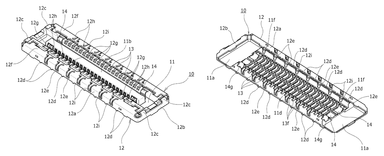
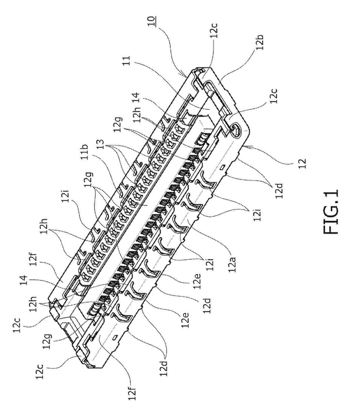
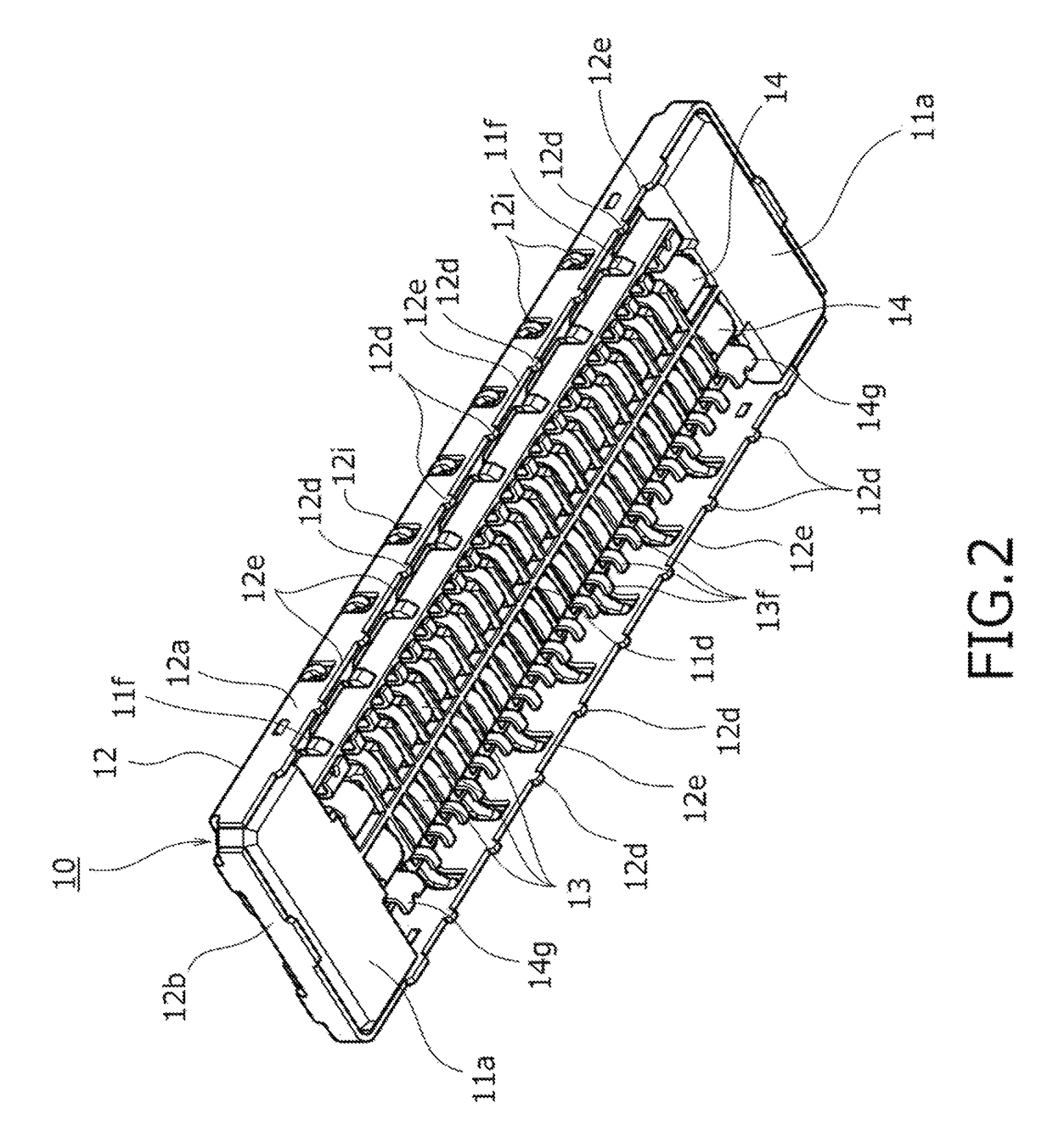
[0059]A board-connecting electric connector device according to the embodiment of the present invention shown in the drawings is used for, for example, electrically connecting wiring boards, which are disposed in an electric device of various types such as a mobile phone, a smartphone, or a tablet-type computer, to each other and is composed of a receptacle connector 10 serving as a first electric connector shown in FIG. 1 to FIG. 9 and a plug connector 20 serving as a second electric connector shown in FIG. 10 to FIG. 18. The receptacle connector (first electric connector) 10 is mounted on a first wiring board P1 shown in, for example, FIG. 30; the plug connector (second electric connector) 20 is mounted on a second wiring board P2 shown in, for example FIG. 31; and, when both of the electric connectors 10 and...


PUM


Abstract

Electromagnetic shielding about both of electric connectors, which are in a mutually mated state, can be sufficiently carried out by a simple configuration. Shield wall portions composed of electrically-conductive members opposed to contact connecting portions (board connecting portions) of a plurality of contact members arranged in multipolar shapes are provided; electromagnetic shielding functions with respect to the contact connecting portions in the respective electric connectors are obtained well by the respective shield wall portions; and, when both of the electric connectors are mated with each other, the shield wall portions are configured to be in an inner / outer double disposition relation in which they are opposed to each other and efficiently block the gaps between the shield wall portions and wiring boards so that sufficient EMI measures can be expected.

Description

BACKGROUND OF THE INVENTION[0001]Field of the Invention[0002]The present invention relates to board-connecting electric connectors mutually connected in a state in which they are mounted on wiring boards.[0003]Description of Related Art[0004]Generally, in various electric devices, board-connecting electric connector devices referred to as stacking connectors, etc. are widely used. In the board-connecting electric connector device, for example, above a first electric connector (receptacle connector) coupled to a first wiring board, a second electric connector (plug connector) coupled to a second wiring board is disposed so as to be opposed thereto, the second electric connector in the upper side is pushed in so as to be lowered toward the first electric connector in the lower side from such a vertically opposed state, and both of the electric connectors are brought into a mutually mated state as a result, thereby electrically connecting the first and second wiring boards to each othe...

Claims


Application Information

Patent Timeline
Patent Type & Authority Patents(United States)
IPC IPC(8): H01R13/6581H01R13/631H01R12/71H01R13/52H01R13/6594
CPCH01R13/6581H01R12/716H01R13/6594H01R13/631H01R13/5213
Inventor OZEKI, KOSUKE
Owner DAIICHI SEIKO CO LTD
Why Eureka
Try Eureka