Liquid crystal display device

a liquid crystal display and display device technology, applied in non-linear optics, instruments, optics, etc., can solve the problems of low efficiency of light utilization of liquid crystal display devices, etc., and achieve the effect of suppressing blur and improving response characteristics

Active Publication Date: 2019-01-08
SHARP KK
View PDF9 Cites 1 Cited by
  • Summary
  • Abstract
  • Description
  • Claims
  • Application Information

AI Technical Summary

Benefits of technology

[0023]According to an embodiment of the present invention, there is provided a liquid crystal display device which excels in both response characteristics and display quality and which is suitable for use as a see-through display, such that blur can be suppressed in a mode of displaying under which the background is allowed to be seen while controlling transmittance in a pixel-by-pixel manner.

Problems solved by technology

In the case where a liquid crystal display device is used for a see-through display, its low efficiency of light utilization will be a detriment.
The reasons for the low efficiency of light utilization of a liquid crystal display device are the color filters and polarizing plates, which are provided in generic liquid crystal display devices.
However, under the field sequential method, the liquid crystal display device is required to have a rapid response.

Method used


Image

  • Liquid crystal display device
  • Liquid crystal display device
  • Liquid crystal display device

Examples


Embodiment Construction

[0048]Hereinafter, with reference to the drawings, embodiments of the present invention will be described. Note that the present invention is not limited to the following embodiments.

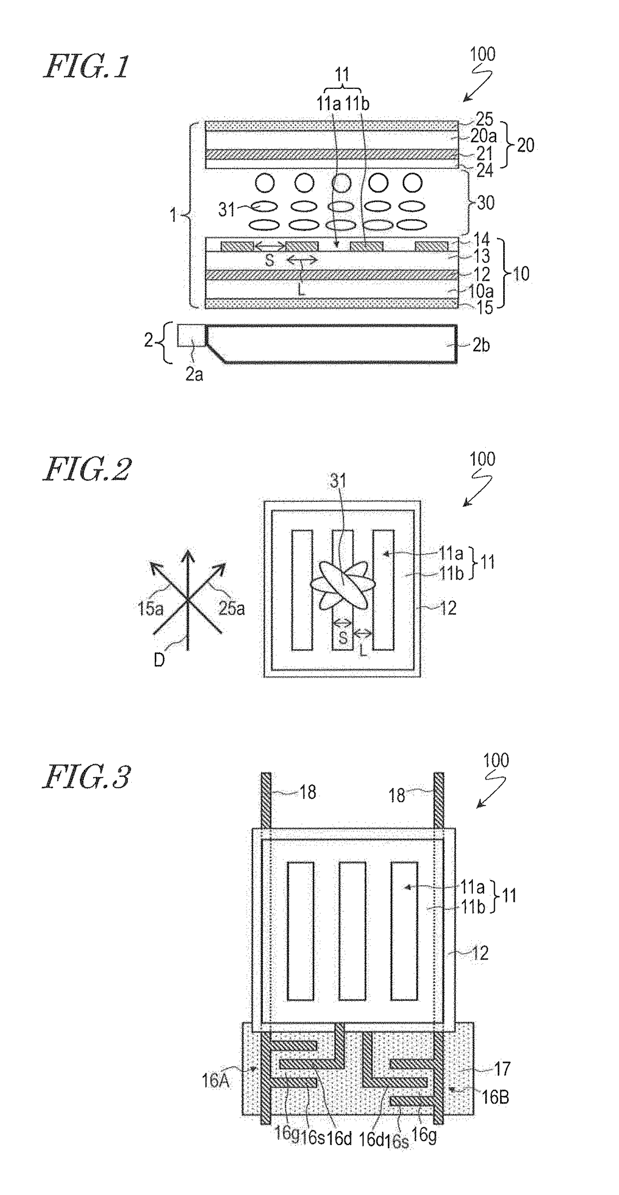
[0049]With reference to FIG. 1 and FIG. 2, a liquid crystal display device 100 according to the present embodiment will be described. FIG. 1 is a cross-sectional view schematically showing the liquid crystal display device 100, and FIG. 2 is a plan view schematically showing the liquid crystal display device 100.

[0050]As shown in FIG. 1, the liquid crystal display device 100 includes a liquid crystal display panel 1 and an illumination element 2. Moreover, the liquid crystal display device 100 includes a plurality of pixels arranged in a matrix array. The liquid crystal display device 100 performs multicolor displaying by the field sequential method, as will be described later.

[0051]The liquid crystal display panel 1 includes a first substrate 10 and a second substrate 20 opposing each other, and a liqu...


PUM

PropertyMeasurementUnit
widthaaaaaaaaaa
widthaaaaaaaaaa
angleaaaaaaaaaa

Abstract

A liquid crystal display device (100) includes a liquid crystal display panel (1) and an illumination element (2), and is capable of switching between: a first mode of displaying in which displaying is performed by using a plurality of color rays emitted from the illumination element; and a second mode of displaying in which the background is allowed to be perceived, with no color rays being emitted from the illumination element. Each pixel is, under the first mode of displaying, capable of switchably presenting a black displaying state with a vertical field being generated across the liquid crystal layer (30), a white displaying state with a lateral field being generated across the liquid crystal layer, or a transparent displaying state of allowing the rear face side to be visible in a see-through manner with no voltage applied to the liquid crystal layer, and, under the second mode of displaying, capable of switchably presenting a black displaying state with a vertical field being generated across the liquid crystal layer, a transparent displaying state of allowing the rear face side to be visible in a see-through manner with no voltage being applied to the liquid crystal layer, a white displaying state with essentially only a vertical field being generated across the liquid crystal layer, or an intermediate level displaying state with essentially only a vertical field being generated across the liquid crystal layer.

Description

TECHNICAL FIELD[0001]The present invention relates to a liquid crystal display device, and more particularly to a liquid crystal display device which is suitable for use as a see-through display.BACKGROUND ART[0002]In recent years, see-through displays have been attracting attention as the display devices for information display systems or digital signage. In a see-through display, the background (i.e., the rear-face side of the display panel) is visible in a see-through manner, thereby conducting displaying such that information which is displayed by the display panel is overlaid on the background. Thus, a see-through display has good appeal and eyecatchingness. Application of see-through displays to showcases and show windows has also been proposed.[0003]In the case where a liquid crystal display device is used for a see-through display, its low efficiency of light utilization will be a detriment. The reasons for the low efficiency of light utilization of a liquid crystal display ...

Claims


Application Information

Patent Timeline
Patent Type & Authority Patents(United States)
IPC IPC(8): G02F1/1343G02F1/1335G02F1/1362
CPCG02F1/1343G02F1/1362G02F1/133602G02F1/134309G02F1/133514G02F2001/134381G02F1/134381
Inventor SASAKI, TAKAHIROAOYAMA, IORIKITA, YUICHIHANAOKA, KAZUTAKAYOSHIDA, HIDEFUMI
Owner SHARP KK
Why Eureka
Try Eureka