Liquid crystal display device

a liquid crystal display and display device technology, applied in static indicating devices, instruments, non-linear optics, etc., can solve the problems of low efficiency of light utilization the need for rapid response of liquid crystal display devices, etc., to achieve the effect of achieving both response characteristics and display quality

Inactive Publication Date: 2016-06-23
SHARP KK
View PDF11 Cites 15 Cited by
  • Summary
  • Abstract
  • Description
  • Claims
  • Application Information

AI Technical Summary

Benefits of technology

[0027]According to an embodiment of the present invention, there is provided a liquid crystal display device which excels in both

Problems solved by technology

In the case where a liquid crystal display device is used for a see-through display, its low efficiency of light utilization will be a detriment.
The reasons for the low efficiency of light utilization of a liquid crystal dis

Method used


Image

  • Liquid crystal display device
  • Liquid crystal display device
  • Liquid crystal display device

Examples


embodiment 1

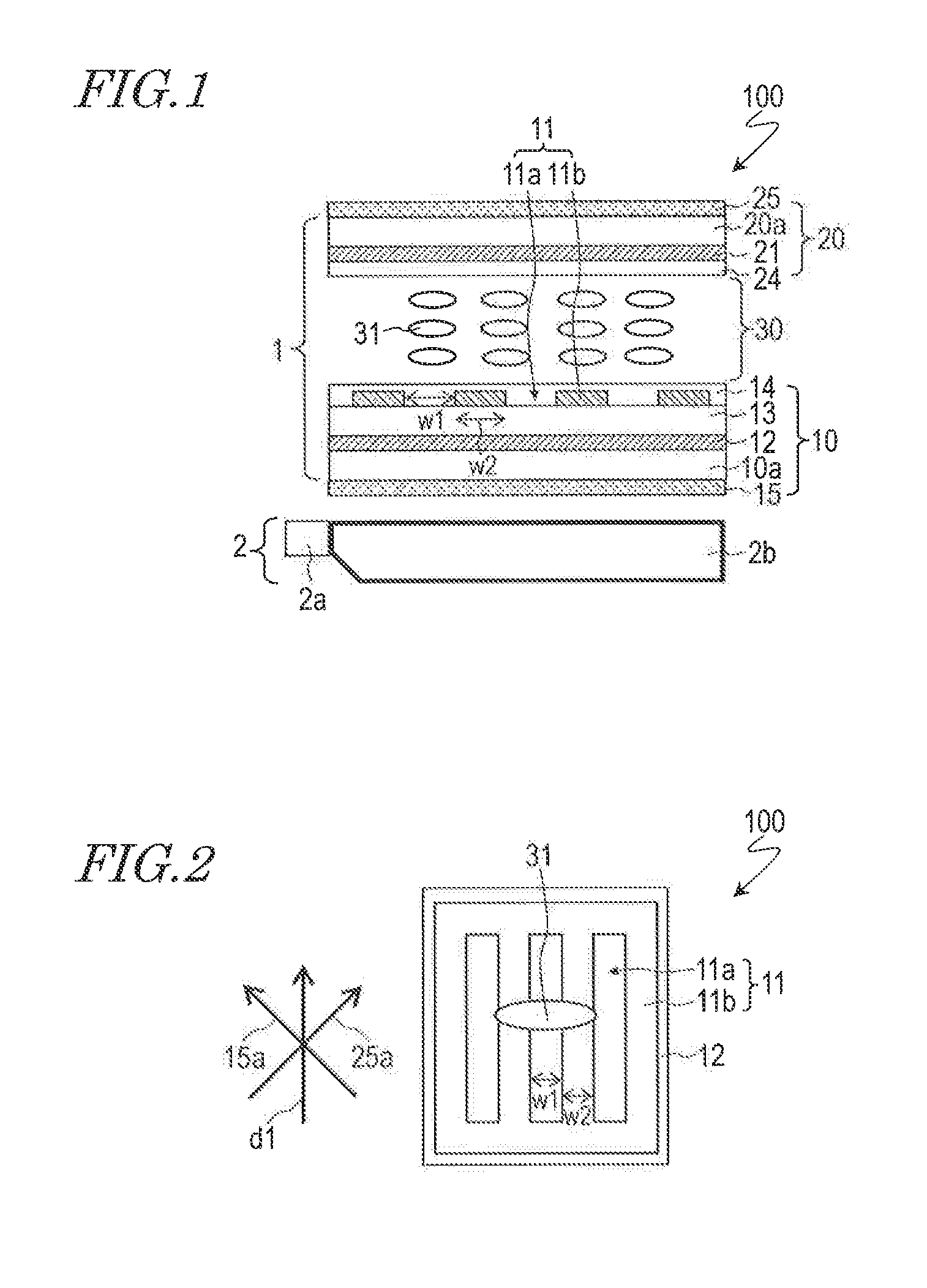
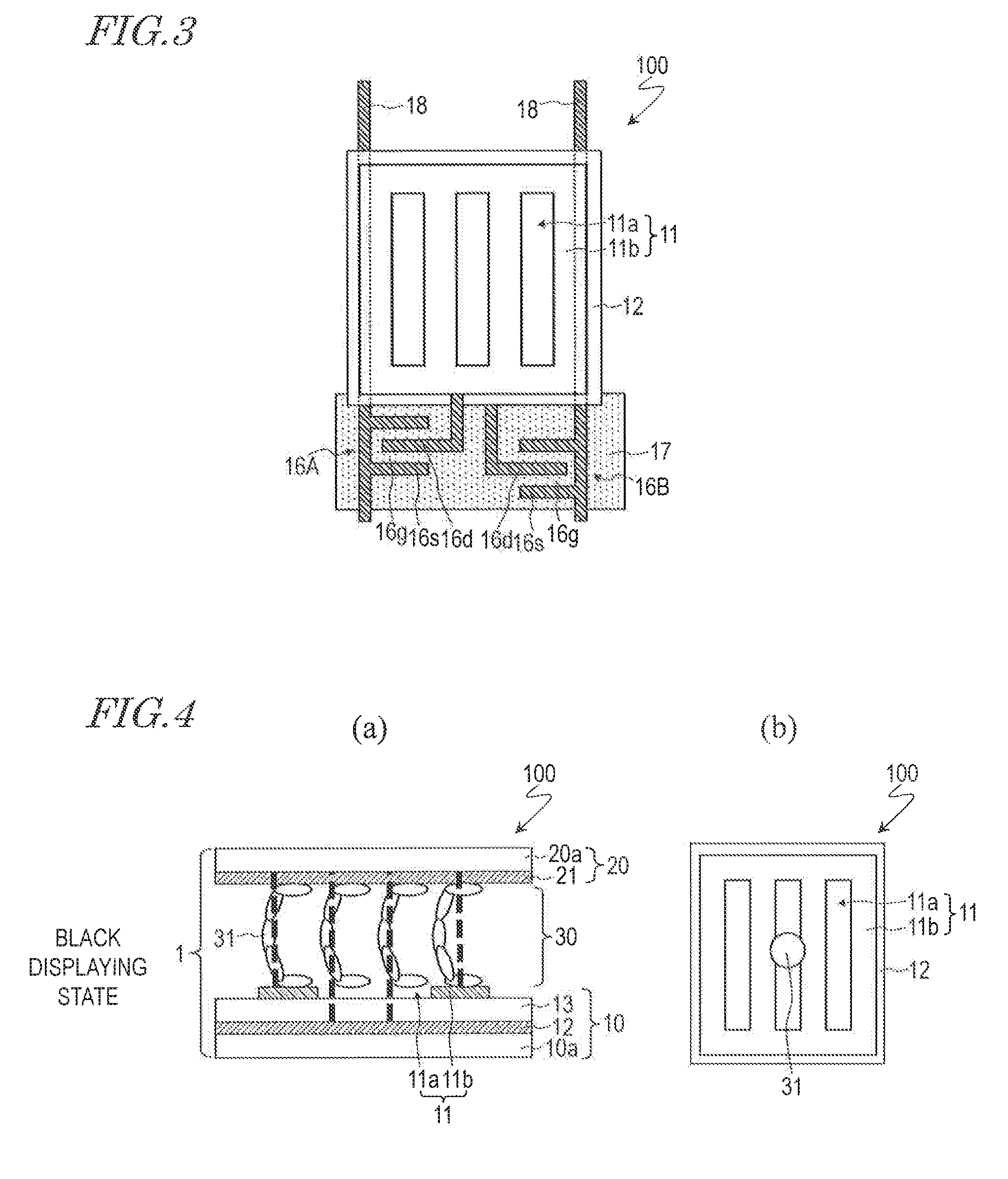
[0048]FIG. 1 and FIG. 2 show a liquid crystal display device 100 according to the present embodiment. FIG. 1 is a cross-sectional view schematically showing the liquid crystal display device 100, and FIG. 2 is a plan view schematically showing the liquid crystal display device 100.

[0049]As shown in FIG. 1, the liquid crystal display device 100 includes a liquid crystal display panel 1 and an illumination element 2. Moreover, the liquid crystal display device 100 includes a plurality of pixels arranged in a matrix array. FIG. 1 and FIG. 2 show an electrode structure corresponding to one pixel. As will be described later, the liquid crystal display device 100 performs multicolor displaying by the field sequential method.

[0050]The liquid crystal display panel 1 includes a first substrate 10 and a second substrate 20 opposing each other, and a liquid crystal layer 30 interposed between the first substrate 10 and the second substrate 20. Hereinafter, between the first substrate 10 and th...

embodiment 2

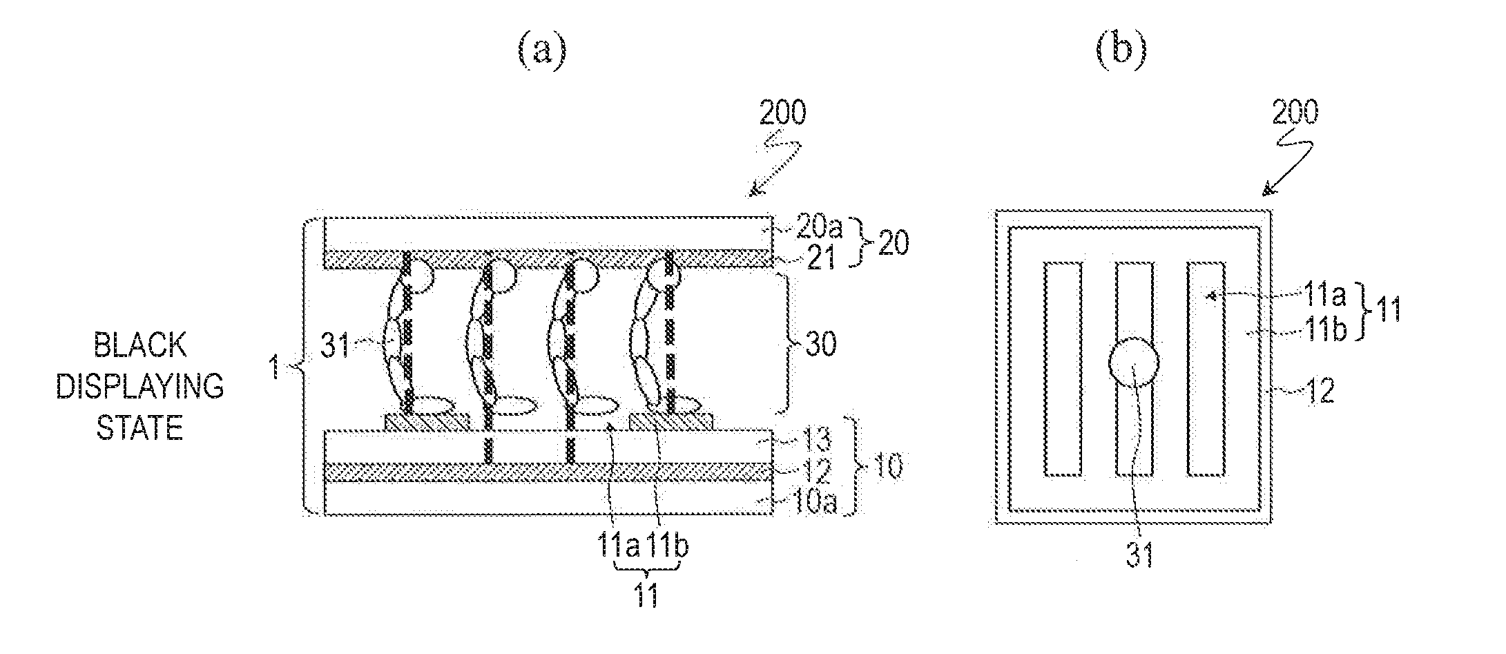
[0093]FIG. 7 and FIG. 8 show a liquid crystal display device 200 according to the present embodiment. FIG. 7 is a cross-sectional view schematically showing the liquid crystal display device 200, and FIG. 8 is a plan view schematically showing the liquid crystal display device 200.

[0094]The liquid crystal display device 200 differs from the liquid crystal display device 100 of Embodiment 1 in that the liquid crystal molecules 31 take a twist alignment in a state where no voltage is applied to the liquid crystal layer 30 (i.e., a state where no electric field is generated).

[0095]Pretilt directions which are respectively defined by the first horizontal alignment film 14 and the second horizontal alignment film 24 of the liquid crystal display device 200 constitute angles of substantially 45° with respect to the direction d1 that the slits 11a in the upper electrode 11 extend. Moreover, the pretilt direction defined by second horizontal alignment film 24 constitutes an angle of 90° wit...


PUM


Abstract

A liquid crystal display device (100) has a liquid crystal display panel (1), which includes a first substrate (10), a second substrate (20), and a liquid crystal layer (30). The first substrate includes a first electrode (11) provided for each pixel, and a second electrode (12) for generating a lateral field across the liquid crystal layer in cooperation with the first electrode, whereas the second substrate includes a third electrode (21) for generating a vertical field across the liquid crystal layer in cooperation with the first electrode and the second electrode. Each pixel is capable of switchably presenting a black displaying state where black displaying is performed with a vertical field being generated across the liquid crystal layer, a white displaying state where white displaying is performed with a lateral field being generated across the liquid crystal layer, or a transparent displaying state where a rear face side of the liquid crystal display panel is visible in a see-through manner with no voltage being applied to the liquid crystal layer.

Description

TECHNICAL FIELD[0001]The present invention relates to a liquid crystal display device, and more particularly to a liquid crystal display device which is suitable for use as a see-through display.BACKGROUND ART[0002]In recent years, see-through displays have been attracting attention as the display devices for information display systems or digital signage. In a see-through display, the background (i.e., the rear-face side of the display panel) is visible in a see-through manner, whereby information to be indicated on the display panel is displayed as if overlaid on the background. Thus, a see-through display has good appeal and eyecatchingness. Application of see-through displays to showcases and show windows has also been proposed.[0003]In the case where a liquid crystal display device is used for a see-through display, its low efficiency of light utilization will be a detriment. The reasons for the low efficiency of light utilization of a liquid crystal display device are the colo...

Claims


Application Information

Patent Timeline
IPC IPC(8): G02F1/1343G02F1/1333G02F1/1335G02F1/139G02F1/1337
CPCG02F1/134363G02F1/134336G02F1/1396G02F1/1337G02F1/133528G02F1/133345G02F2001/133622G02F2001/134381G02F2001/133738G02F2001/133746G02F2001/133531G02F2001/13706G02F1/133621G02F1/134309G02F1/1393G02F2203/34G02F1/133622G02F1/133738G02F1/134381G02F1/13706G02F1/133531G02F1/133746
Inventor KITA, YUICHINAKATANI, YOSHIKIIMAOKU, TAKAOAOYAMA, IORIYOSHIOKA, TAKATOMO
Owner SHARP KK
Why Eureka
Try Eureka