This helps you quickly interpret patents by identifying the three key elements:
Problems solved by technology
Method used
Benefits of technology
Benefits of technology
The present invention provides a liquid crystal display device with excellent response characteristics and display quality, suitable for use as a see-through display.
Problems solved by technology
In the case where a liquid crystal display device is used for a see-through display, its low efficiency of light utilization will be a detriment.
The reasons for the low efficiency of light utilization of a liquid crystal display device are the color filters and polarizing plates, which are provided in generic liquid crystal display devices.
Image
Click on the blue label to locate the original text in one second.
Reading with bidirectional positioning of images and text.
Examples
embodiment 1
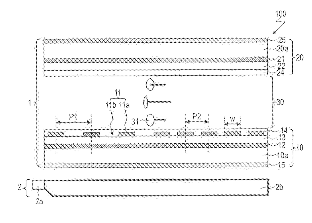
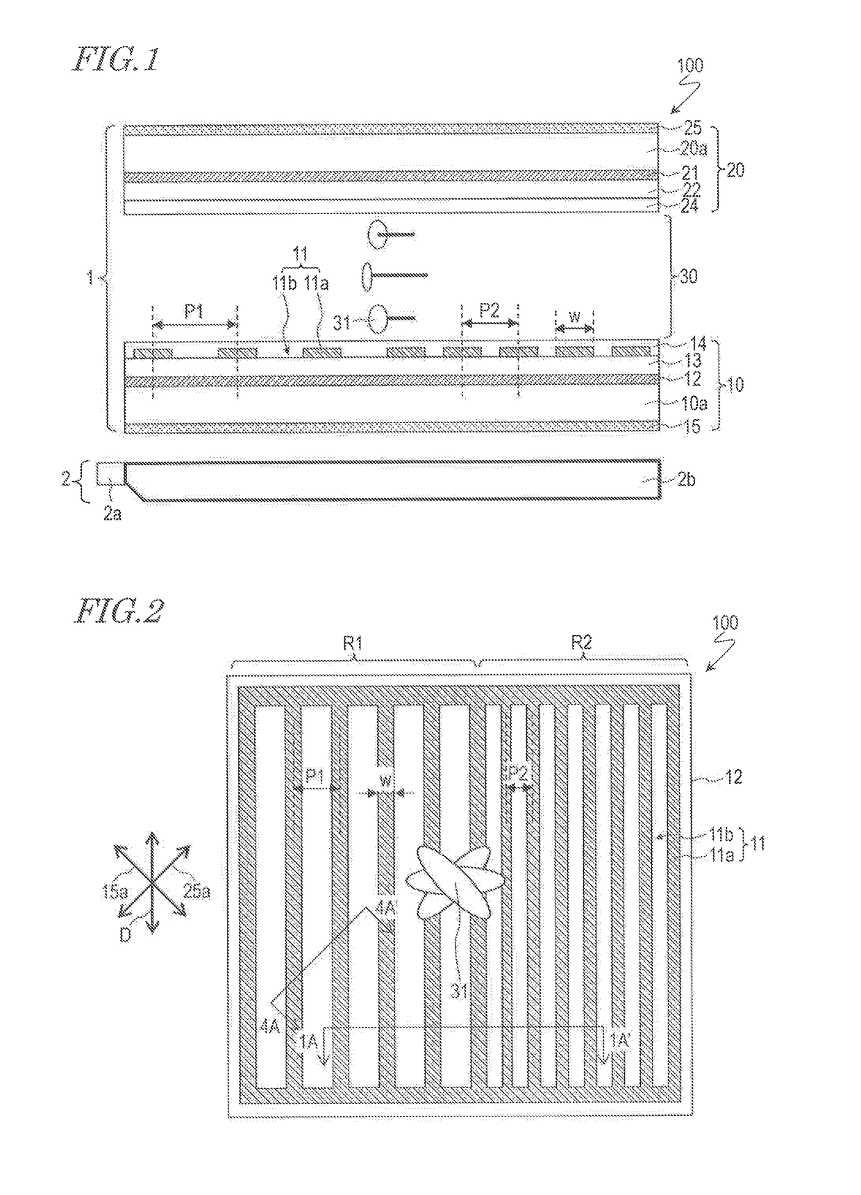
[0054]With reference to FIG. 1 and FIG. 2, a liquid crystal display device 100 according to the present embodiment will be described. FIG. 1 and FIG. 2 are, respectively, a cross-sectional view and a plan view schematically showing the liquid crystal display device 100. FIG. 2 illustrates a region corresponding to one pixel, whereas FIG. 1 illustrates a cross section along line 1A-1A′ in FIG. 2.
[0055]As shown in FIG. 1, the liquid crystal display device 100 includes a liquid crystal display panel 1 and an illumination element 2. Moreover, the liquid crystal display device 100 includes a plurality of pixels arranged in a matrix array. As will be described later, the liquid crystal display device 100 performs multicolor displaying by the field sequential method.
[0056]The liquid crystal display panel 1 includes a first substrate 10 and a second substrate 20 opposing each other, and a liquid crystal layer 30 interposed between the first substrate 10 and the second substrate 20. Hereinaf...
embodiment 2
[0116]With reference to FIG. 13, a liquid crystal display device 100 according to the present embodiment will be described. FIG. 13 is a plan view schematically showing the liquid crystal display device 200, illustrating a region corresponding to one pixel. The following description will be mainly directed to aspects in which the liquid crystal display device 200 differs from the liquid crystal display device 100 of Embodiment 1 (the same is also true of any embodiment to follow).
[0117]In the liquid crystal display device 200 of the present embodiment, the construction of the upper electrode is different from that in the liquid crystal display device 100 of Embodiment 1. In the present embodiment, the plurality of linear portions 11a of the upper electrode 11 are arranged so as to extend along a plurality of directions (specifically, two), as shown in FIG. 13. In other words, the plurality of linear portions 11a include: two or more linear portions 11a1 which extend along a first di...
embodiment 3
[0122]With reference to FIG. 15, a liquid crystal display device 300 according to the present embodiment will be described. FIG. 15 is a plan view schematically showing the liquid crystal display device 300, illustrating a region corresponding to one pixel.
[0123]In the liquid crystal display device 300 of the present embodiment, the construction of the upper electrode is different from that in the liquid crystal display device 100 of Embodiment 1. In the present embodiment, the plurality of linear portions 11a of the upper electrode 11 are arranged so as to extend along a plurality of directions (specifically, two), and to result in a plurality of pitches (which herein is four), as shown in FIG. 15.
[0124]The plurality of linear portions 11a include: two or more linear portions 11a1 which extend along a first direction D1 (which herein is the vertical direction on the display surface); and two or more linear portions 11a2 which extend along a second direction D2 (which herein is the ...
PUM
Abstract
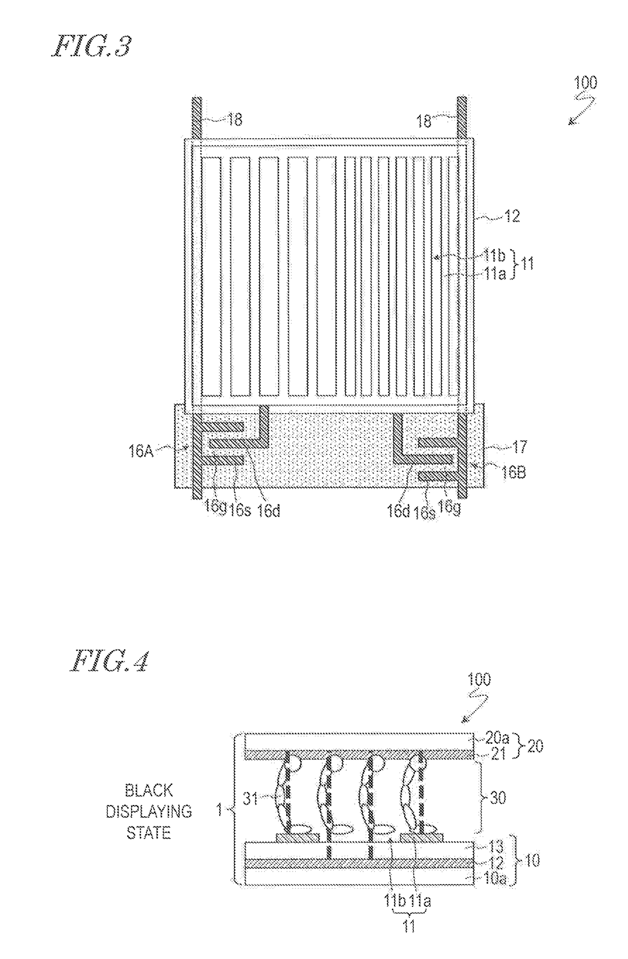
A liquid crystaldisplay device (100) includes a liquid crystal display panel (1) including a first substrate (10), a second substrate (20), and a liquid crystal layer (30). The first substrate includes a first electrode (11) provided for each pixel, and a second electrode (12) for generating a lateral field across the liquid crystal layer in cooperation with the first electrode. The second substrate includes a third electrode (21) for generating a vertical field across the liquid crystal layer in cooperation with the first electrode and the second electrode. Each pixel is capable of switchably presenting a black displaying state where a vertical field is generated across the liquid crystal layer, a white displaying state where a lateral field is generated across the liquid crystal layer, and a transparent displaying state where a rear face side of the liquid crystal display panel is visible in a see-through manner with no voltage being applied to the liquid crystal layer. The first electrode includes a plurality of linear portions (11a), the plurality of linear portions being arranged so that at least one of the following exists in a plurality: the direction that the linear portions extend and the pitch of the linear portions.
Description
TECHNICAL FIELD[0001]The present invention relates to a liquid crystal display device, and more particularly to a liquid crystal display device which is suitable for use as a see-through display.BACKGROUND ART[0002]In recent years, see-through displays have been attracting attention as the display devices for information display systems or digital signage. In a see-through display, the background (i.e., the rear-face side of the display panel) is visible in a see-through manner, whereby a novel manner of display that was never possible with conventional display devices can be achieved. Thus, a see-through display has good appeal and eyecatchingness. Application of see-through displays to showcases and show windows has also been proposed.[0003]In the case where a liquid crystal display device is used for a see-through display, its low efficiency of light utilization will be a detriment. The reasons for the low efficiency of light utilization of a liquid crystal display device are the...
Claims
Application Information
Patent Timeline
Application Date:The date an application was filed.
Publication Date:The date a patent or application was officially published.
First Publication Date:The earliest publication date of a patent with the same application number.
Issue Date:Publication date of the patent grant document.
PCT Entry Date:The Entry date of PCT National Phase.
Estimated Expiry Date:The statutory expiry date of a patent right according to the Patent Law, and it is the longest term of protection that the patent right can achieve without the termination of the patent right due to other reasons(Term extension factor has been taken into account ).
Invalid Date:Actual expiry date is based on effective date or publication date of legal transaction data of invalid patent.

