Transflective liquid crystal display device and method of forming the same

a liquid crystal display and reflector technology, applied in static indicating devices, instruments, non-linear optics, etc., can solve problems such as poor rubbing and dark-state light leakage, and achieve the effect of reducing the occurrence of poor rubbing and dark-state light leakage, and simplifying technical difficulties

Active Publication Date: 2019-03-19
TCL CHINA STAR OPTOELECTRONICS TECH CO LTD
View PDF28 Cites 0 Cited by
  • Summary
  • Abstract
  • Description
  • Claims
  • Application Information

AI Technical Summary

Benefits of technology

[0008]An object of the present invention is to provide a transflective LCD device and a method of forming the same as a simple solution to transflective display. The present invention can realize a single-cell transflective LCD, simplify technical difficulties, and reduce occurrences of poor rubbing and dark-state light leakage caused by a difference in thickness of two cells.
[0028]In contrast to prior art, the present invention has an advantage of dividing a first substrate and a second substrate into the transmissive area and the reflective area. The transmissive and reflective areas on a first alignment film and second alignment film are aligned by different angles, thus the liquid crystal molecules in the liquid crystal layer of the corresponding transmissive and reflective areas are tilted by different pretilt angles. Therefore, a beam of light going one-way through the liquid crystal layer corresponding to the transmissive area generates the same phase retardation as making a round-trip through the liquid crystal layer corresponding to the reflective area. The present invention can thus realize the single-cell transflective LCD, simplify technical difficulties, and reduce occurrences of poor rubbing and dark-state light leakage caused by the difference in thickness of two cells.

Problems solved by technology

In addition, an initial alignment of liquid crystal molecules is usually done by rubbing, which poses a technical challenge in the design of cells as a difference in thickness of the two cells will lead to poor rubbing and dark-state light leakage.

Method used


Image

  • Transflective liquid crystal display device and method of forming the same
  • Transflective liquid crystal display device and method of forming the same
  • Transflective liquid crystal display device and method of forming the same

Examples


Embodiment Construction

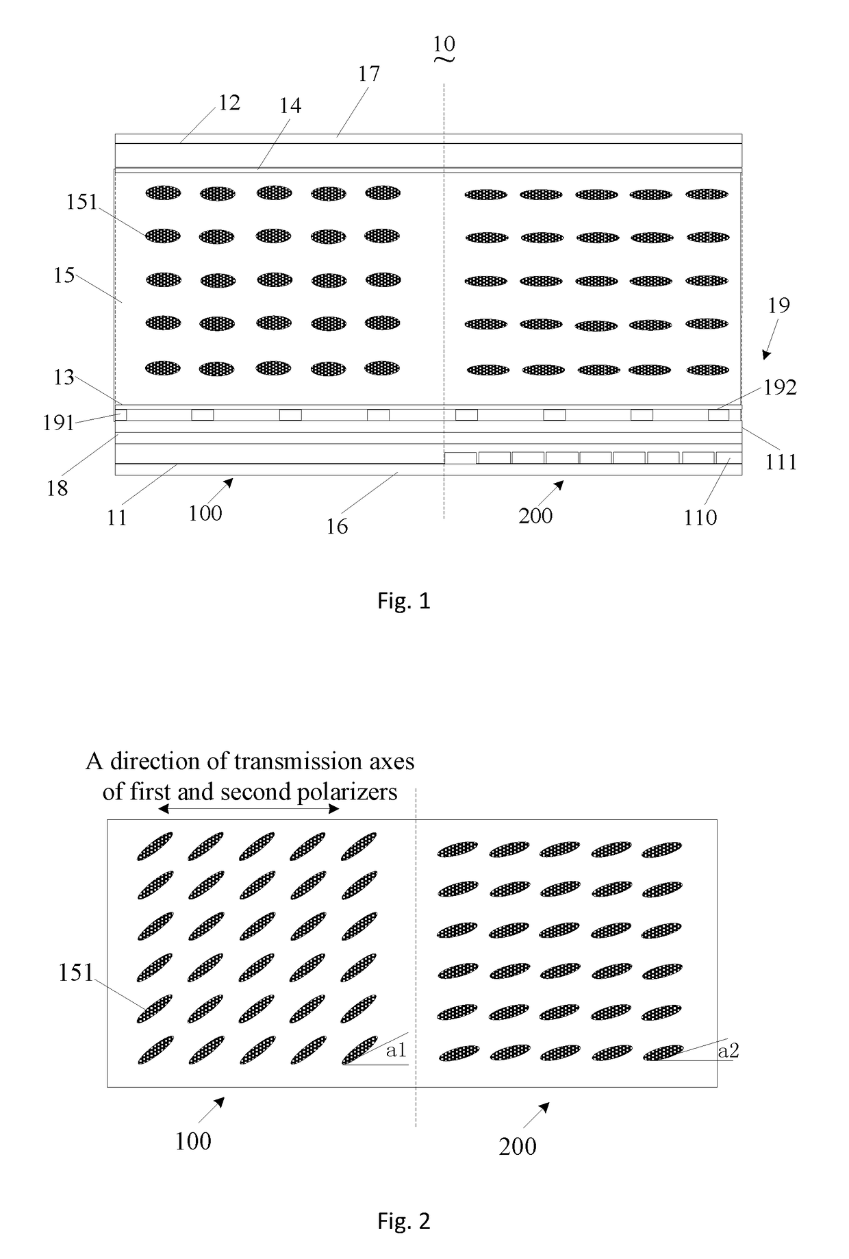
[0034]Referring to FIGS. 1 and 2, FIG. 1 is a longitudinal section diagram of a transflective LCD device according to an embodiment of the present invention and FIG. 2 is a top view of the liquid crystal molecules when no voltage is applied on the transflective LCD device of the present invention. The transflective LCD device 10 of the present invention comprises a first substrate 11, a second substrate 12, a first alignment film 13, a second alignment film 14, and a liquid crystal layer 15.

[0035]The first substrate 11 and the second substrate 12, which may be made of glass materials, are installed facing each other.

[0036]The first alignment film 13 is installed on one side of the first substrate 11, which faces the second substrate 12. The second alignment film 14 is installed on one side of the second substrate 12, which faces the first substrate 11.

[0037]The first alignment film 13 and the second alignment film 14, after being irradiated to trigger a photoreaction, generate aniso...


PUM

PropertyMeasurementUnit
pretilt angleaaaaaaaaaa
pretilt angle a2aaaaaaaaaa

Abstract

A transflective LCD device and a method of forming the same are proposed. The transflective LCD includes a first substrate, a second substrate, a first alignment film, a second alignment film and a liquid crystal layer. The first substrate and the second substrate are divided into a transmissive area and a reflective area, in which areas of the first alignment film and the second alignment film are configured respectively by different aligning angles. The liquid crystal molecules in the liquid crystal layer corresponding to the transmissive area and the reflective area are tilted by different pretilt angles. Therefore, light going one-way through the liquid crystal layer corresponding to the transmissive area generates the same phase retardation as making a round-trip through the liquid crystal layer corresponding to the reflective area.

Description

CROSS REFERENCE TO RELATED APPLICATIONS[0001]This is a divisional application of co-pending U.S. patent application Ser. No. 14 / 426,237, filed on Mar. 5, 2015, which is a national stage of PCT Application No. PCT / CN2014 / 095386, filed on Dec. 29, 2014, claiming foreign priority of Chinese Patent Application No. 201410790215.8, filed on Dec. 17, 2014.FIELD OF THE INVENTION[0002]The present invention relates to display technology, and more specifically, to a transflective liquid crystal display (LCD) device and its forming method.DESCRIPTION OF THE PRIOR ART[0003]In general, a LCD panel comprises a color film substrate and an array substrate combined together, encasing a liquid crystal layer in between. Given that liquid crystal molecules emit no light, a display panel needs a light source to show images. Based on the type of light sources adopted, LCD devices can be categorized as transimissive LCD, reflective LCD or transflective LCD.[0004]A transmissive LCD panel mostly adopts a bac...

Claims


Application Information

Patent Timeline
Patent Type & Authority Patents(United States)
IPC IPC(8): G02F1/1335G02F1/1337G09G3/36G02F1/136
CPCG02F1/133555G02F1/136G02F1/1335G09G3/3648G02F1/133788G09G2300/08G02F2001/133761G09G2300/0456G02F1/133761
Inventor XIE, CHANG
Owner TCL CHINA STAR OPTOELECTRONICS TECH CO LTD
Why Eureka
Try Eureka