Unlock instant, AI-driven research and patent intelligence for your innovation.

Liquid ejecting apparatus, control device, recording system, control program of liquid ejecting apparatus, recording medium, and image forming method

a liquid ejecting and liquid technology, applied in the field control device, recording system, control program of liquid ejecting apparatus, recording medium, etc., can solve the problems of reduced print quality, increased weight per single ink droplet, and increased structure complexity, so as to reduce the deviation of the landing position and improve the effect of print quality

Active Publication Date: 2019-05-14
SEIKO EPSON CORP
View PDF3 Cites 0 Cited by
  • Summary
  • Abstract
  • Description
  • Claims
  • Application Information

AI Technical Summary

Benefits of technology

This approach effectively reduces landing position deviations and maintains consistent printing density by synchronizing discharge timings and waveforms for nozzles, enhancing print quality without increasing ink droplet weight or complexity.

Problems solved by technology

In this manner, in a case in which ink droplets are discharged at the same time from consecutive nozzles, landing position deviation occurs between the landing position of the ink droplet which is discharged from the nozzle of an end portion and the landing position of an ink droplet which is discharged from a nozzle other than an end portion, and there is a problem in that the print quality is reduced.
As in JP-A-2007-144787, although it is possible to adjust the flight direction of an ink droplet which is discharged from a nozzle of an end portion of a consecutive nozzle group by providing two pressure generating elements for one nozzle, two pressure generating elements are necessary for one nozzle and there is a problem in that the structure becomes complicated.
Furthermore, a method of suppressing landing position deviation by increasing the flight speed of the ink droplets which are discharged from the nozzles of the end portions among consecutive nozzles which discharge ink droplets in comparison to the flight speed of the ink droplets which are ejected from the nozzles other than those of the end portions is conceivable; however, due to increasing the flight speed of the ink droplets, the weight per single ink droplet also increases and there is a problem in that the printing density increases and the print quality is reduced.
This problem exists not only in an ink jet recording apparatus but also similarly in liquid ejecting apparatuses which eject liquids other than ink.

Method used


Image

  • Liquid ejecting apparatus, control device, recording system, control program of liquid ejecting apparatus, recording medium, and image forming method
  • Liquid ejecting apparatus, control device, recording system, control program of liquid ejecting apparatus, recording medium, and image forming method
  • Liquid ejecting apparatus, control device, recording system, control program of liquid ejecting apparatus, recording medium, and image forming method

Examples


first embodiment

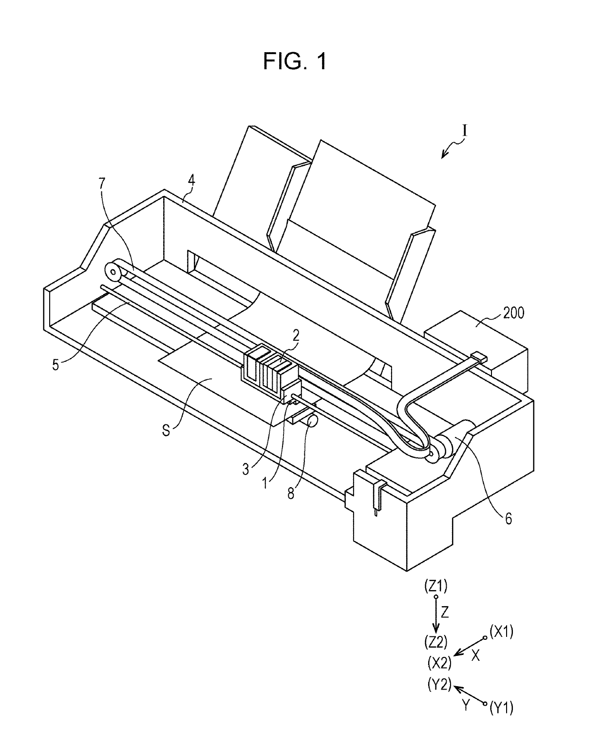
[0048]FIG. 1 is a diagram illustrating the schematic configuration of an ink jet recording apparatus which is an example of the liquid ejecting apparatus according to the first embodiment of the invention.

[0049]As illustrated in FIG. 1, an ink jet recording apparatus I which is an example of the liquid ejecting apparatus of the present embodiment includes an ink jet recording head 1 (hereinafter also referred to as the recording head 1) which ejects an ink which serves as a liquid as ink droplets. The recording head 1 is mounted on a carriage 3 and the carriage 3 is provided on a carriage shaft 5 which is attached to an apparatus main body 4 such that the carriage 3 is capable of moving in an axial direction of the carriage shaft 5. An ink cartridge 2 which configures a liquid supply unit is provided in the carriage 3 to be attachable and detachable.

[0050]The carriage 3 to which the recording head 1 is mounted moves reciprocally along the carriage shaft 5 due to the driving force of...


PUM


Abstract

A liquid ejecting apparatus includes a nozzle row in which nozzles which discharge a liquid are provided to line up, drive elements for discharging the liquid from the nozzles, and a control unit which drives the drive elements, in which the control unit selects the nozzles which are necessary from the nozzle row based on recording data and causes the liquid to be discharged from the nozzles which are selected at a predetermined timing, and in which a nozzle group is configured by consecutive nozzles which are adjacent to each other among the nozzles which are selected at each timing and a discharge timing of the liquid to be discharged from the nozzles of end portions of the nozzle group is caused to deviate with respect to the discharge timing of the liquid to be discharged from the nozzles other than those of the end portions.

Description

[0001]The entire disclosure of Japanese Patent Application No. 2017-007058, filed Jan. 18, 2017 is expressly incorporated by reference herein.BACKGROUND1. Technical Field[0002]The present invention relates to a liquid ejecting apparatus which ejects a liquid from nozzles, a control device which controls the liquid ejecting apparatus, a recording system which includes the control device and the liquid ejecting apparatus, a control program which controls the liquid ejecting apparatus, a recording medium which stores the control program, and an image forming method of the liquid ejecting apparatus.2. Related Art[0003]An ink jet recording apparatus which causes ink droplets to be ejected as the liquid to perform printing on a medium such as paper or a recording sheet is known as an example of the liquid ejecting apparatus.[0004]An ink jet recording head which is installed on the ink jet recording apparatus includes flow paths which communicate with nozzles, and drive elements such as pi...

Claims


Application Information

Patent Timeline
Patent Type & Authority Patents(United States)
IPC IPC(8): B41J2/045B41J2/155
CPCB41J2/04573B41J2/04508B41J2/155B41J2/04588B41J2/04593B41J2/04581
Inventor MIYAGISHI, AKIRA
Owner SEIKO EPSON CORP