Inkjet printing apparatus

a printing apparatus and inkjet technology, applied in the direction of printing, power drive mechanism, spacing mechanism, etc., can solve the problems variable ejection amount or the like, comparatively difficult to deal with the case of uneven density generation, etc., to suppress the deviation of landing position and reduce density unevenness

Inactive Publication Date: 2009-03-05
CANON KK
View PDF5 Cites 30 Cited by
  • Summary
  • Abstract
  • Description
  • Claims
  • Application Information

AI Technical Summary

Benefits of technology

[0017]An object of the present invention is to provide an inkjet printing apparatus capable of reducing an unevenness of density by suppressing landing position deviation due to a difference in distance between the print head and the printing medium in the printing medium conveying direction.

Problems solved by technology

However, variation in manufacturing the print head or the like causes variation in ejection amount or the like.
However, in the landing position adjustment using the ejection timing described above, it is comparatively difficult to deal with the case where an amount of landing position deviation differs in a conveying direction of the printing medium.
As a result, the unevenness of density is caused to be generated by deviation of a dot formation position in the conveying direction.
As a result, the unevenness of density is caused to be generated by deviation of dots formed by the landing inks.
As mentioned above, when the distance between the print head and the printing medium is different between the upstream side and the downstream side in the printing medium conveying direction, the unevenness of density due to the landing position deviation is caused to occur also by the fact that the distance between the landing positions of the main droplet and the satellite of the ink each ejected is different between the upstream side and the downstream side.
However, in this case, distances between the landing positions of the main droplet and the satellite can not be changed.
However, such adjusting method does not necessarily reflect actual distance between the print head and the printing medium, and accordingly, in some cases, the unevenness of density caused by the landing position deviation can not be eliminated, as a result.

Method used


Image

  • Inkjet printing apparatus
  • Inkjet printing apparatus
  • Inkjet printing apparatus

Examples


first embodiment

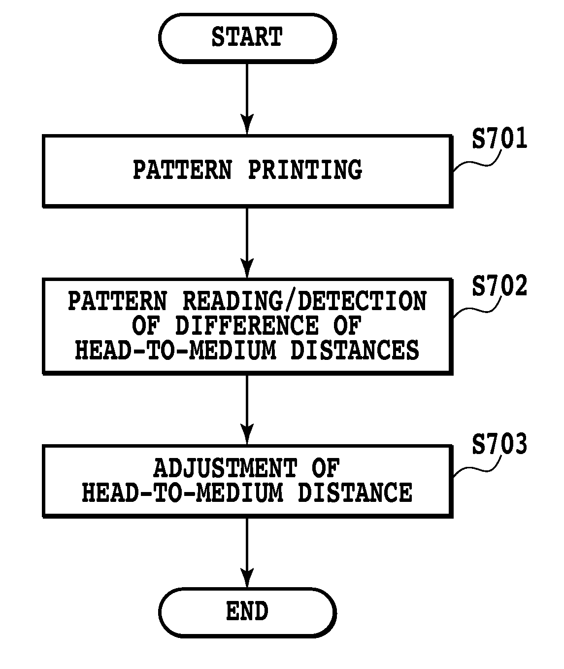
[0056]FIG. 7 is a flowchart showing measurement of the head-to-medium distance and processing of adjustment of the head-to-medium distance based on the measurement according to one embodiment of the present invention.

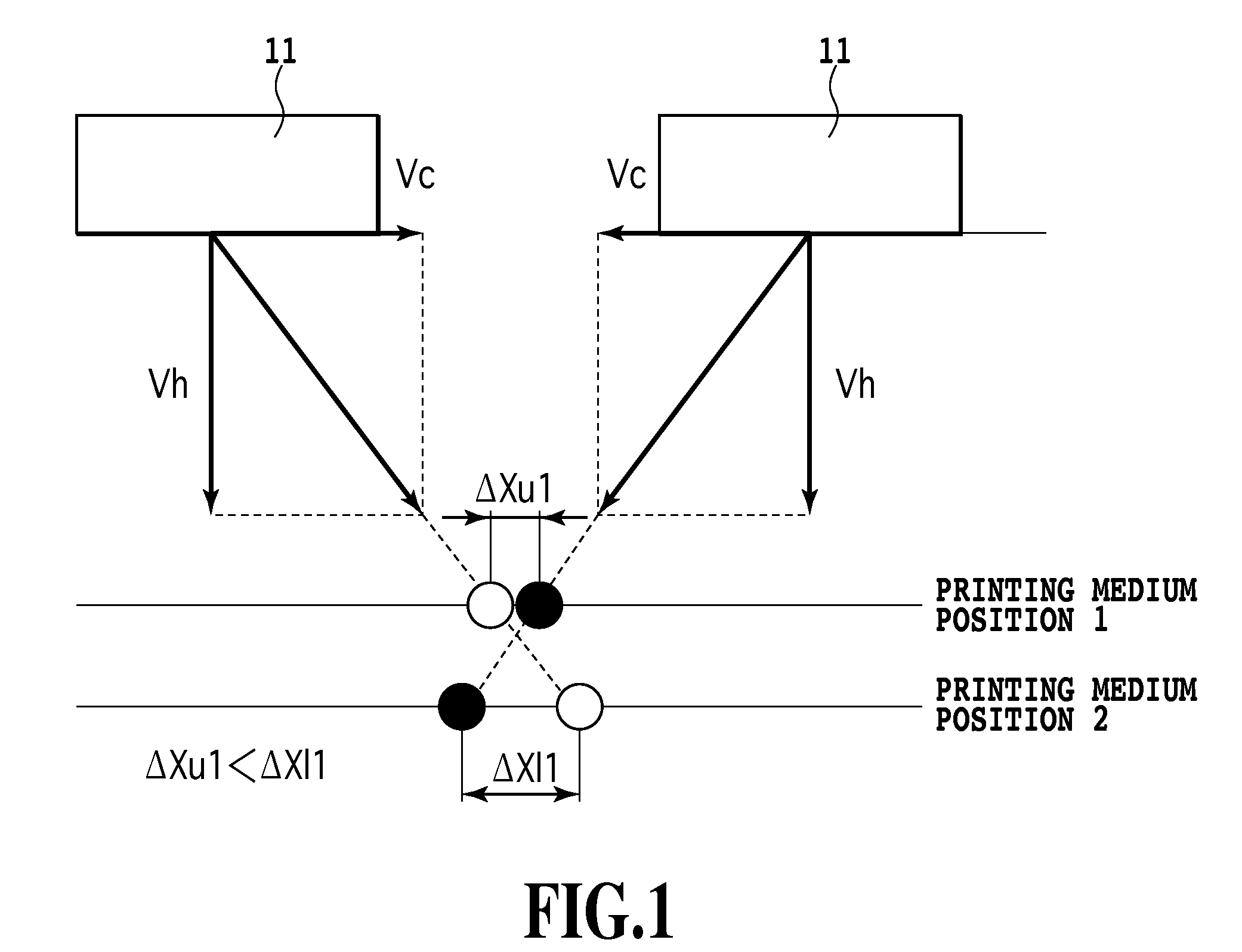
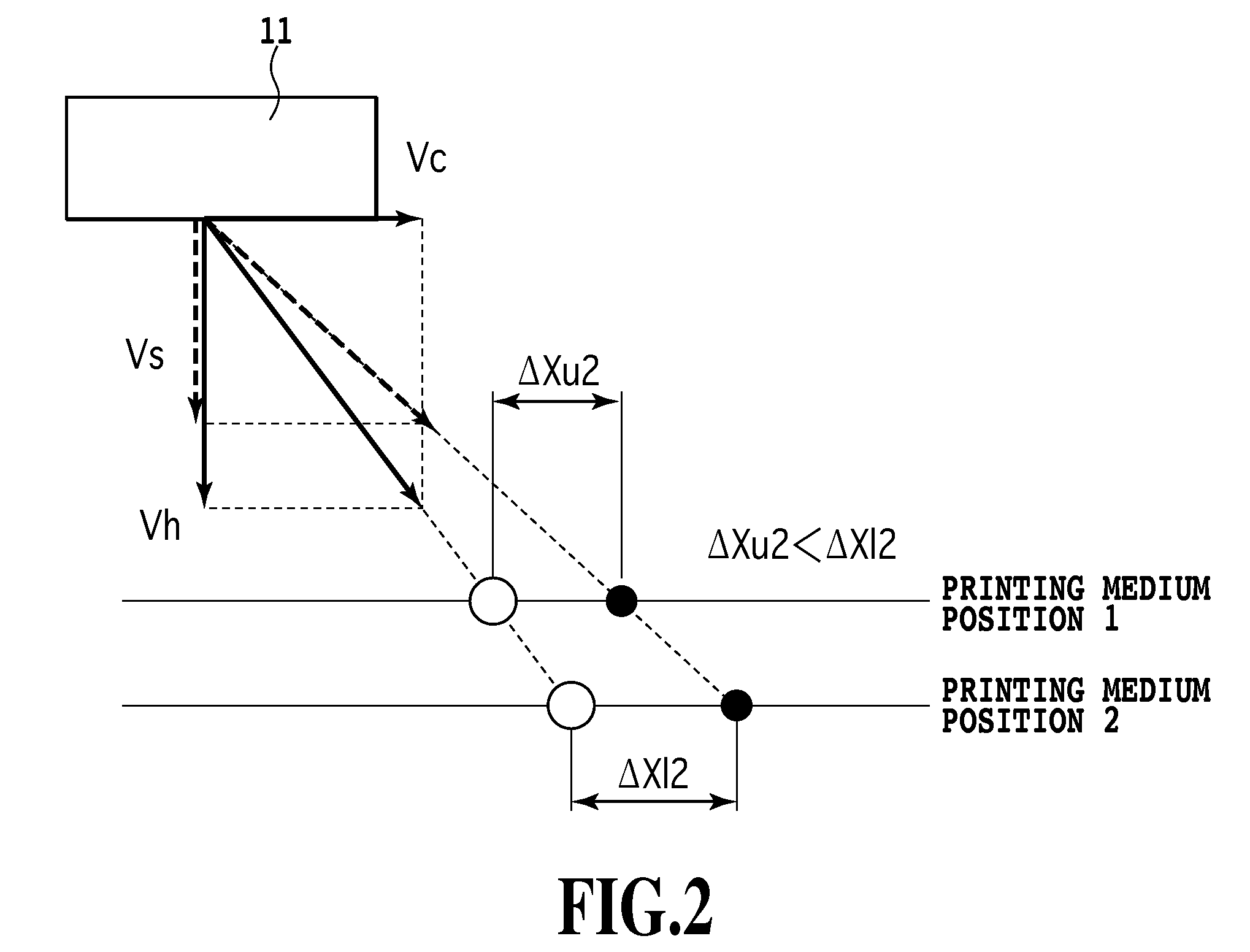
[0057]In FIG. 7, first, a predetermined pattern for detecting a difference of the head-to-medium distances is printed (S701). At this time, in a case where there is a difference between the sheet-to-medium distance at the position of the upstream side ejection port and that at the position of the downstream side ejection port, a difference occurs in distances between formed dots in mutual head-to-medium distances, as described before in FIGS. 1 and 2.

[0058]FIG. 8 is a diagram illustrating that state, and shows that distances between dots printed by the respective reciprocating printings is different between the upstream side and the downstream side. As shown in FIG. 8, the head-to-medium distance between the downstream side ejection port and the printing medium is Δy1, ...


PUM


Abstract

In an inkjet printing apparatus, uneven density is reduced while suppressing a landing position deviation caused by a difference of head-to-medium distances in a printing medium conveying direction. Specifically, predetermined patterns for detecting a difference of the head-to-medium distances are printed. Reading of the patterns is performed and then a detection of a difference between the head-to-medium distances is performed based on the reading result. Then, adjustment of the head-to-medium distance is performed based on the difference between the head-to-medium distances detected. Specifically, the respective head-to-medium distances at the upstream side ejection port and the downstream side ejection port are made equal by changing an attitude of the print head.

Description

BACKGROUND OF THE INVENTION[0001]1. Field of the Invention[0002]The present invention relates to an inkjet printing apparatus, and specifically, relates to a configuration for adjusting a distance between a print head and a printing medium such as a printing sheet.[0003]2. Description of the Related Art[0004]In recent years, comparatively inexpensive office automation equipments such as personal computers, word processors, are used generally; and accompanied with that, various printing apparatuses for printing information input by the office automation equipments, and technologies for increasing printing speed-up and technologies for achieving high printing quality have been developed rapidly. Among the printing apparatuses, a serial printer using dot matrix printing system receives attention as an apparatus for realizing high speed and high printing quality with low cost. In addition, as a technology for performing printing with high quality, for instance, a multi-pass printing sys...

Claims


Application Information

Patent Timeline
Patent Type & Authority Applications(United States)
IPC IPC(8): B41J25/308
CPCB41J25/308B41J19/145
Inventor KIDA, AKIRA
Owner CANON KK
Why Eureka
Try Eureka