Image recording apparatus

An image recording and image technology, applied in the direction of electrography, electrical recording technology using charge patterns, and equipment using charge pattern electric recording technology, etc., can solve the problems of position deviation, replacement of recording heads, etc.

Inactive Publication Date: 2005-07-20
OLYMPUS CORP
View PDF2 Cites 5 Cited by
  • Summary
  • Abstract
  • Description
  • Claims
  • Application Information

AI Technical Summary

Problems solved by technology

In addition, no matter how high the mounting accuracy is during manufacturing, positional shift may occur in subsequent use, or the recording head may need to be replaced in some cases, so it cannot be dealt with.

Method used


Image

  • Image recording apparatus
  • Image recording apparatus
  • Image recording apparatus

Examples


Embodiment Construction

[0046] Hereinafter, embodiments of the present invention will be described with reference to the drawings.

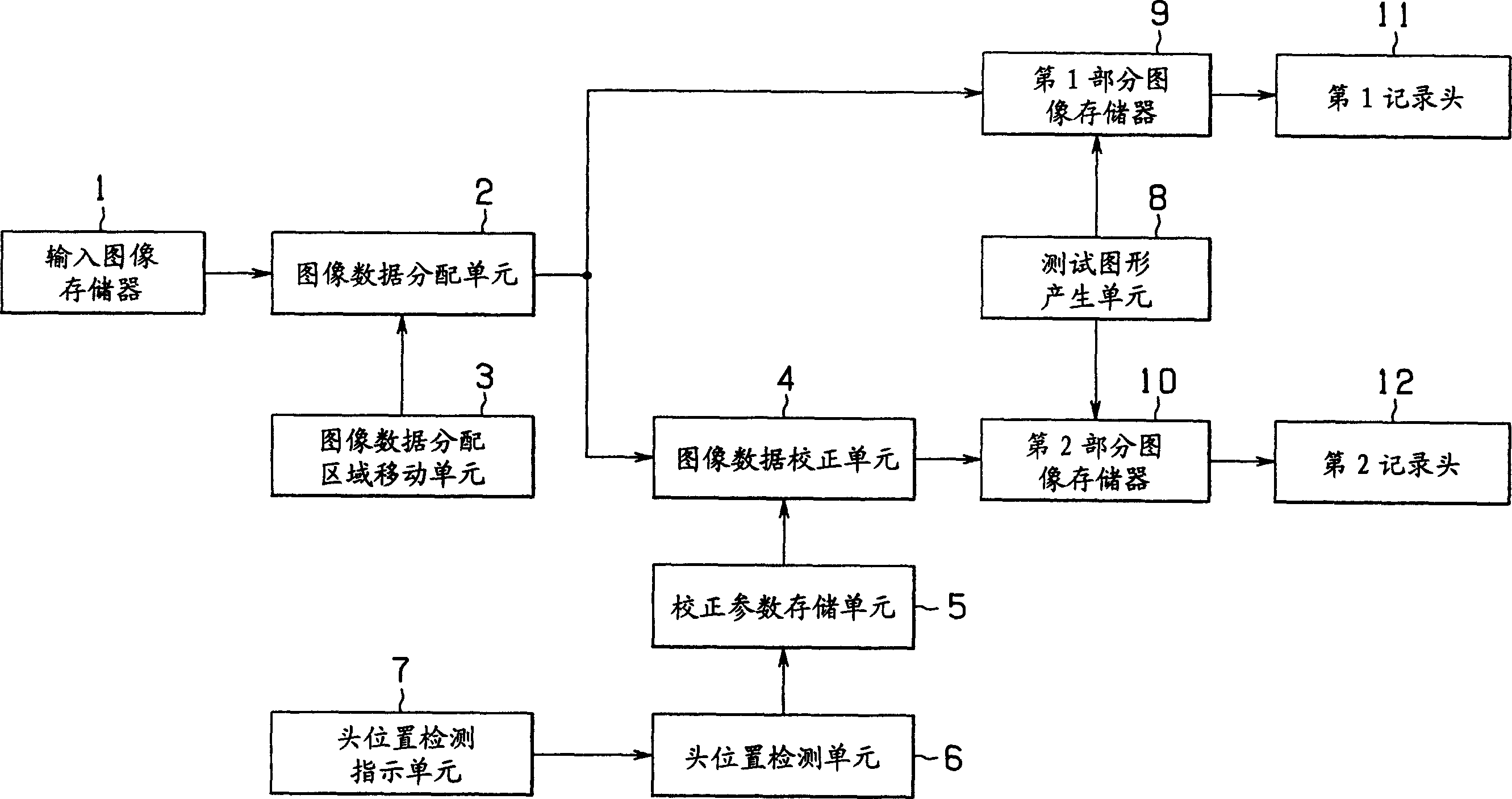
[0047] Figure 1 to Figure 13 represents an embodiment of the present invention, figure 1 is a block diagram showing the configuration of the image recording device.

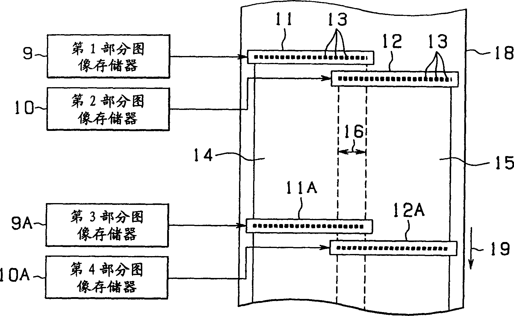
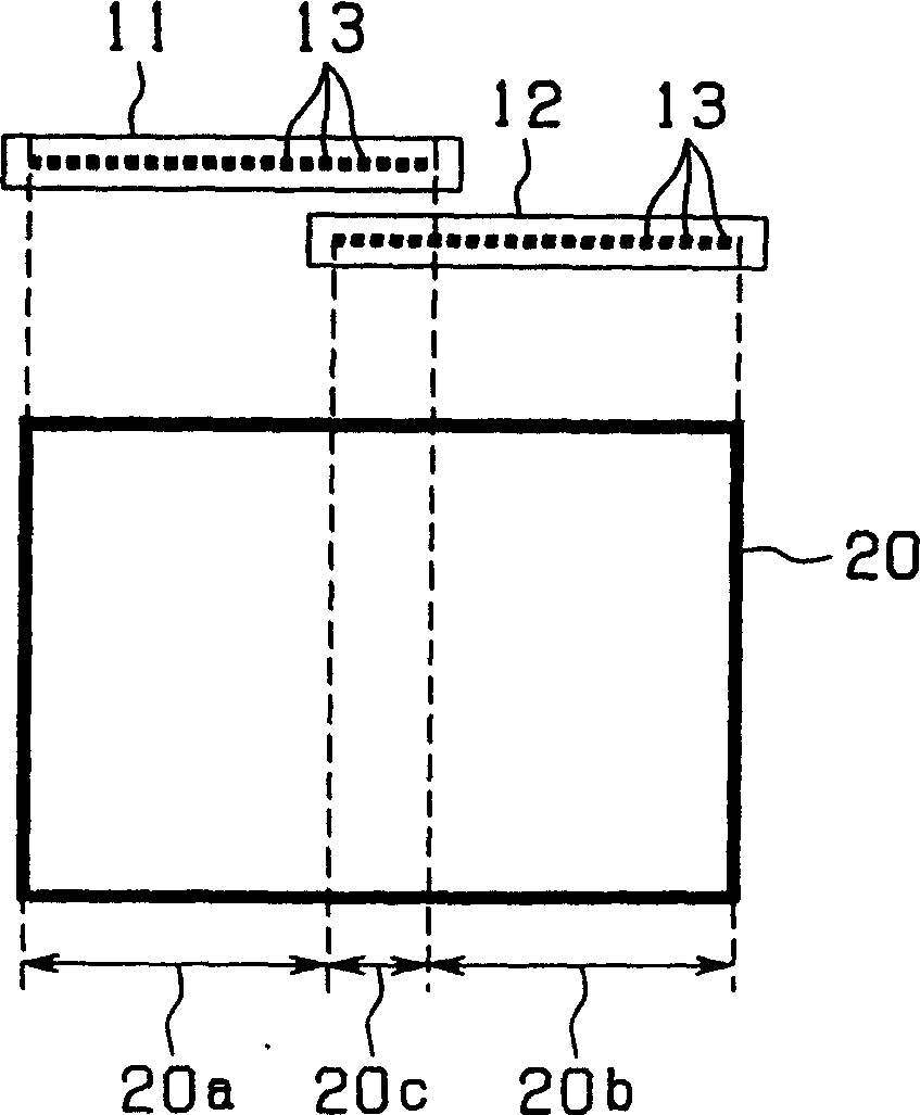
[0048] Such as figure 1 As shown, the image recording device is composed of the following parts: an input image memory 1, which holds image data to be printed; an image data distribution unit 2, which distributes the image data read from the input image memory 1 into Image data for the first recording head 11 and the second recording head 12; the image data distribution area setting unit, that is, the image data distribution area moving unit 3, is set according to the manner described later, so that the image data distribution area overlaps Move by row in the area, wherein the image data allocation area is the area where the image data of the same pixel is all allocated to the first recording head 11 a...


PUM


Abstract

An image recording device comprises: a first and second recording heads (11, 12) formed of recording elements cyclically arrayed, which are continuously arrayed with an overlapped region; image data distributing means (2) for distributing image data to these recording heads (11, 12); image data distribution region variation means (3) for setting an image data distribution region where the image data of each pixel is distributed to both the recording heads (11, 12) by the image data distributing means (2); correction parameter storage means (5) for storing a correction parameter for correcting the difference in the image density properties between the image data distribution region and the other region due to phase difference between the recording heads (11, 12); and image data correcting means (4) for correcting the image data in the image data distribution region based upon the correction parameter.

Description

technical field [0001] The present invention relates to an image recording device, and more particularly to an image recording device for recording an image composed of a set of pixels row by row based on image data. Background technique [0002] Conventionally, image recording devices such as printers and facsimiles often use recording heads such as thermal heads and inkjet heads that are configured by arranging a plurality of recording elements. [0003] Specifically, this type of recording head is configured by arranging the above-mentioned recording elements in a direction perpendicular to the feeding direction of recording paper, and performs recording by line. [0004] Therefore, when the recording width in the row direction is long, a recording head in which recording elements are arranged over a length equal to or greater than the recording width is used, but such a long recording head has a problem of high cost due to low manufacturing yield. [0005] Therefore, it...

Claims


Application Information

Patent Timeline
Patent Type & Authority Applications(China)
IPC IPC(8): B41J2/01B41J2/36B41J2/44B41J2/447B41J2/45B41J2/455B41J2/515
CPCB41J2/447B41J2/515G03G15/326G03G15/04045B41J2/2135G03G2215/00582B41J2/155G03G15/5095B41J2/01B41J2/455
Inventor 海老原利行龙田成示井冈健小宫康宏
Owner OLYMPUS CORP
Why Eureka
Try Eureka