Orthodontic practice appliance

a technology for orthodontics and appliances, applied in the field of orthodontics, can solve the problems of high manufacturing cost of the appliance, excessive heat transmission to the metal tooth row, and the resin tooth row of the appliance, and achieve the effect of cheap manufacturing

Active Publication Date: 2019-07-16
NISSIN DENTAL PROD INC
View PDF10 Cites 0 Cited by
  • Summary
  • Abstract
  • Description
  • Claims
  • Application Information

AI Technical Summary

Benefits of technology

[0007]The present invention is intended to provide an orthodontic practice appliance that can be manufactured inexpensively and is improved in terms of the temperature uniformity of the wax gingival part when heated.
[0019]According to the present invention, it is possible to provide an orthodontic practice appliance that can be manufactured inexpensively and is improved in terms of temperature uniformity of the wax orthodontic gingival part when heated.

Problems solved by technology

However, the appliance (1) has a high manufacturing cost.
Furthermore, excessive heat is transmitted to the metal tooth row, and softening of wax around the tooth row is faster than the other areas, and the tooth row may come out.
The resin tooth row of the appliance (2) is poor in thermal conductance, and when the appliance is immersed in hot water with the aim to softening the wax, the surface of the wax is softened before the inside of the wax.
Accordingly, the reproducibility of the smooth movement of the tooth row is low, and the practice effect is low.
The appliance (3) has a lower manufacturing cost than the appliance (1); however, since metal is used in the tooth row, the appliance (3) is still costly.

Method used


Image

  • Orthodontic practice appliance
  • Orthodontic practice appliance
  • Orthodontic practice appliance

Examples


first embodiment

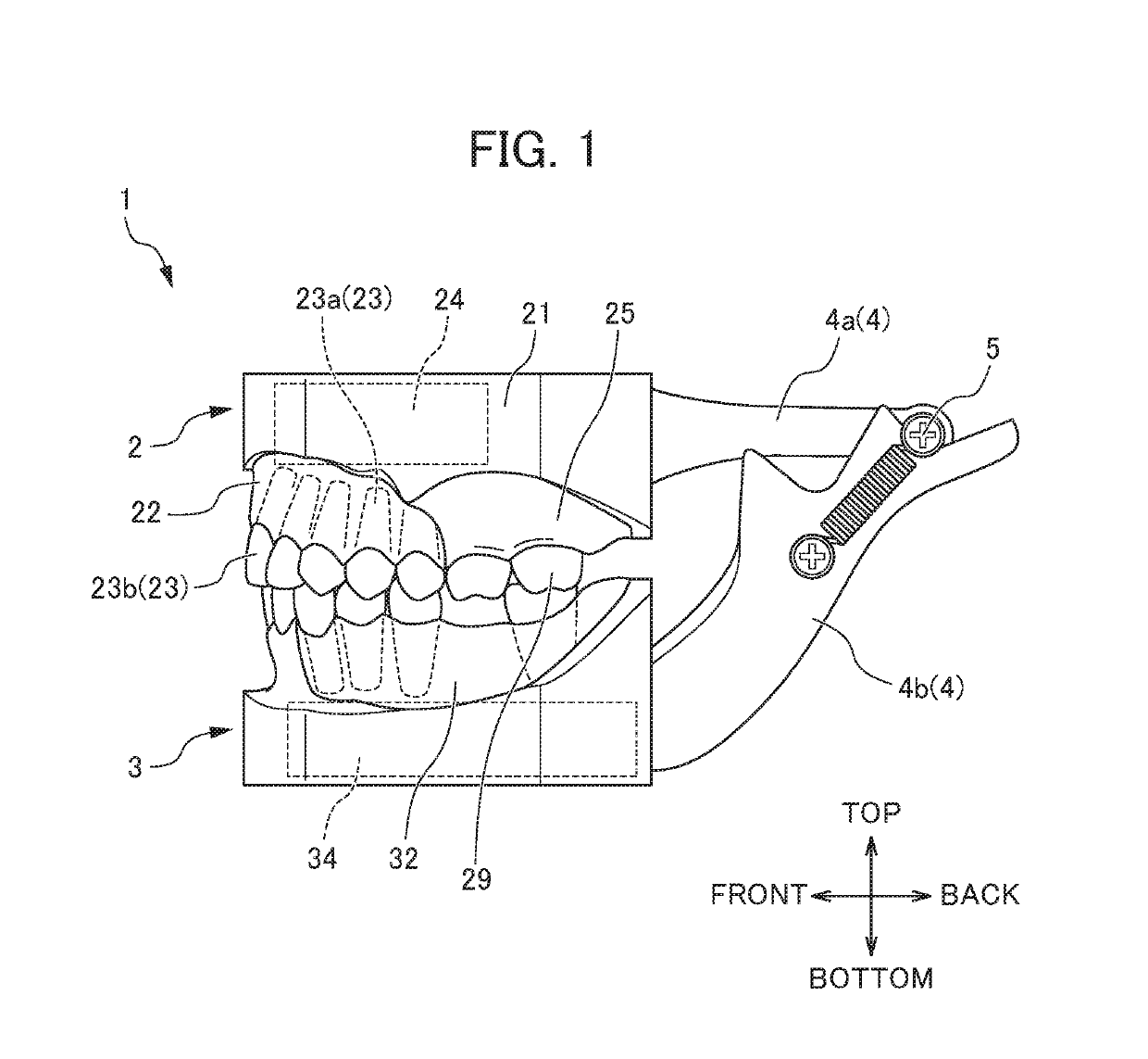
[0036]A first embodiment of the present invention is described below. FIG. 1 is a side view of an orthodontic practice appliance 1. As shown in FIG. 1, the orthodontic practice appliance 1 according to the present embodiment includes an upper orthodontic practice appliance 2 and a lower orthodontic practice appliance 3. However, the orthodontic practice appliance 1 in the present invention is not limited to this and can be configured to include either the upper orthodontic practice appliance 2 or the lower orthodontic practice appliance 3. However, for performing the practice under conditions close to the case of treatment of an actual living body; like the present embodiment, the orthodontic practice appliance 1 is preferably an integrated combination of both the upper orthodontic practice appliance 2 and the lower orthodontic practice appliance 3.

[0037]The upper orthodontic practice appliance 2 and the lower orthodontic practice appliance 3 are each held by a metal holding frame 4...

second embodiment

[0052]The metal plate 24 in the first embodiment has uniform width; however, the width of the metal plate 24 is not limited to this. FIG. 8 is a diagram illustrating a metal plate 242 in a second embodiment. In the second embodiment, the width of the short side of the metal plate 242 is not uniform, and varies according to the length (height) of the root part 23a of the orthodontic tooth row 23. The other configurations are the same as the first embodiment, so a description of the same parts is omitted. Furthermore, the metal plate 242 placed in an upper orthodontic practice appliance is described in the present embodiment; however, the same is true for a metal plate placed in a lower orthodontic practice appliance. The length of the root part 23a in the tooth row is not constant, and varies in some portions. In the second embodiment, the width of the metal plate 242 is changed so that the distance between the root part 23a and the metal plate 242 is kept constant according to the l...

third embodiment

[0053]FIG. 9 is a diagram illustrating a metal plate 243 in a third embodiment. The orthodontic practice appliance in the third embodiment is an orthodontic practice appliance used when orthodontic correction is performed on part of a tooth row. In the third embodiment, the metal plate 243 is placed so as to be along the entire tooth row; however, the width W1 of the portion corresponding to the tooth row 26 not subjected to orthodontic correction is narrower than the width W2 of a portion corresponding to a tooth row 23 subjected to orthodontic correction. The other configurations are the same as the first embodiment, so a description of the same parts is omitted. The metal plate 243 is heated when the orthodontic practice appliance is immersed in hot water. The metal plate 243 extends inside an orthodontic gingival part. Therefore, the orthodontic gingival part is heated not only from the surface thereof in direct contact with the hot water but also from inside thereof by heat tra...


PUM


Abstract

An orthodontic practice appliance (1) in the present invention includes an orthodontic tooth row (23) for orthodontic practice, an orthodontic gingival part (22) that holds the orthodontic tooth row (23) and is softened by the application of heat, and a metal member (24) that is placed inside the orthodontic gingival part (22) and has an exposure portion exposed to the outside. According to the present invention, when the orthodontic practice appliance (1) is immersed in hot water, the exposed metal member (24) is heated. The metal member (24) extends inside the orthodontic gingival part (22). Therefore, the orthodontic gingival part (22) is heated not only from the surface thereof in direct contact with the hot water but also from inside thereof by heat transmitted through the heated metal plate (24). Accordingly, heat is transmitted to the orthodontic gingival part (22) uniformly.

Description

[0001]This application is based on and claims the benefit of priority from Japanese Patent Application Nos. 2016-124298 and 2017-025962, respectively filed on 23 Jun. 2016 and 15 Feb. 2017, the contents of which are incorporated herein by reference.BACKGROUND OF THE INVENTIONField of the Invention[0002]The present invention relates to an orthodontic practice appliance.Related Art[0003]In dental care, the improvement of occlusion or the correction of dentition has been common recently. As a general method for its treatment, there is a method of applying a dental adhesive to the side of the labial region of each tooth row and attaching an orthodontic appliance (brackets) to the tooth row, and fastening a piece of orthodontic wire to the orthodontic appliance along the tooth row, and gradually improving malocclusion by means of the elasticity of the wire. To master such an advanced treatment technique, it is vital to acquire the technique through practice using an orthodontic practice ...

Claims


Application Information

Patent Timeline
Patent Type & Authority Patents(United States)
IPC IPC(8): G09B23/28
CPCG09B23/283G09B23/32G09B23/34
Inventor MARUYAMA, YOUICHIIWASAKI, TERUYUKIMATSUO, KOUSHIROU
Owner NISSIN DENTAL PROD INC
Why Eureka
Try Eureka