Device case, connector, and electronic musical instrument

a technology for connecting devices and electronic musical instruments, applied in the direction of instruments, transducer details, electrophonic musical instruments, etc., can solve the problems of preventing the speaker box from forming an airtight seal around the speakers, and creating a gap between the peripheral portion of the top case and the peripheral portion of the bottom cas

Active Publication Date: 2019-09-17
CASIO COMPUTER CO LTD
View PDF12 Cites 0 Cited by
  • Summary
  • Abstract
  • Description
  • Claims
  • Application Information

AI Technical Summary

Benefits of technology

[0013]In the present invention, the connector is arranged between the peripheral portion of the upper case and the peripheral portion of the lower case such that the connector fits together with an edge of the peripheral portion of the lower case and also contacts an inner surface of the peripheral portion of the upper case, thereby making it possible for the connector to connect together the upper case and the lower case in an airtight manner even when the external shape of the upper case is different than the external shape of the lower case.

Problems solved by technology

However, in this type of musical instrument case, if the external shape of the top case is different than the external shape of the bottom case, then when the top case is placed on top of the bottom case, the peripheral portion of the top case will not fit together with the peripheral portion of the bottom case, thereby creating a gap between the peripheral portion of the top case and the peripheral portion of the bottom case and preventing the speaker box from forming an airtight seal around the speakers.

Method used


Image

  • Device case, connector, and electronic musical instrument
  • Device case, connector, and electronic musical instrument
  • Device case, connector, and electronic musical instrument

Examples


Embodiment Construction

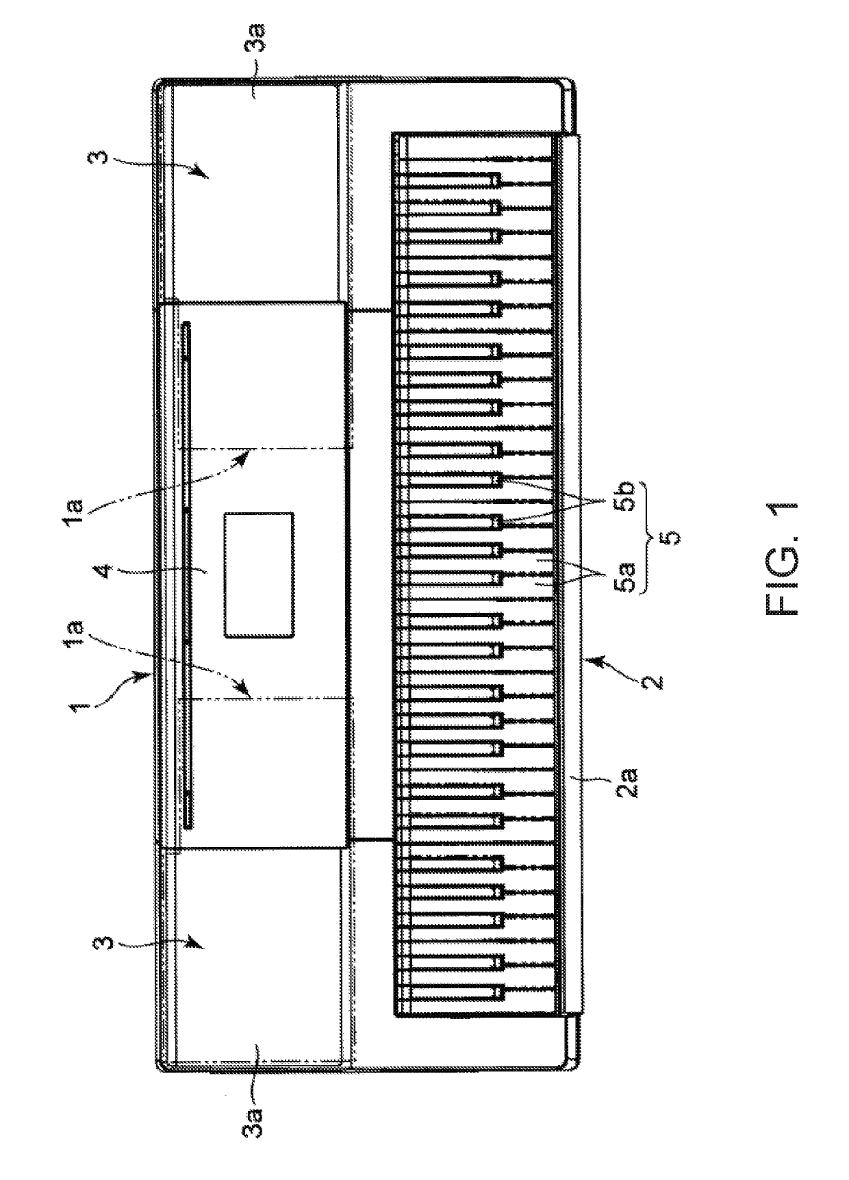
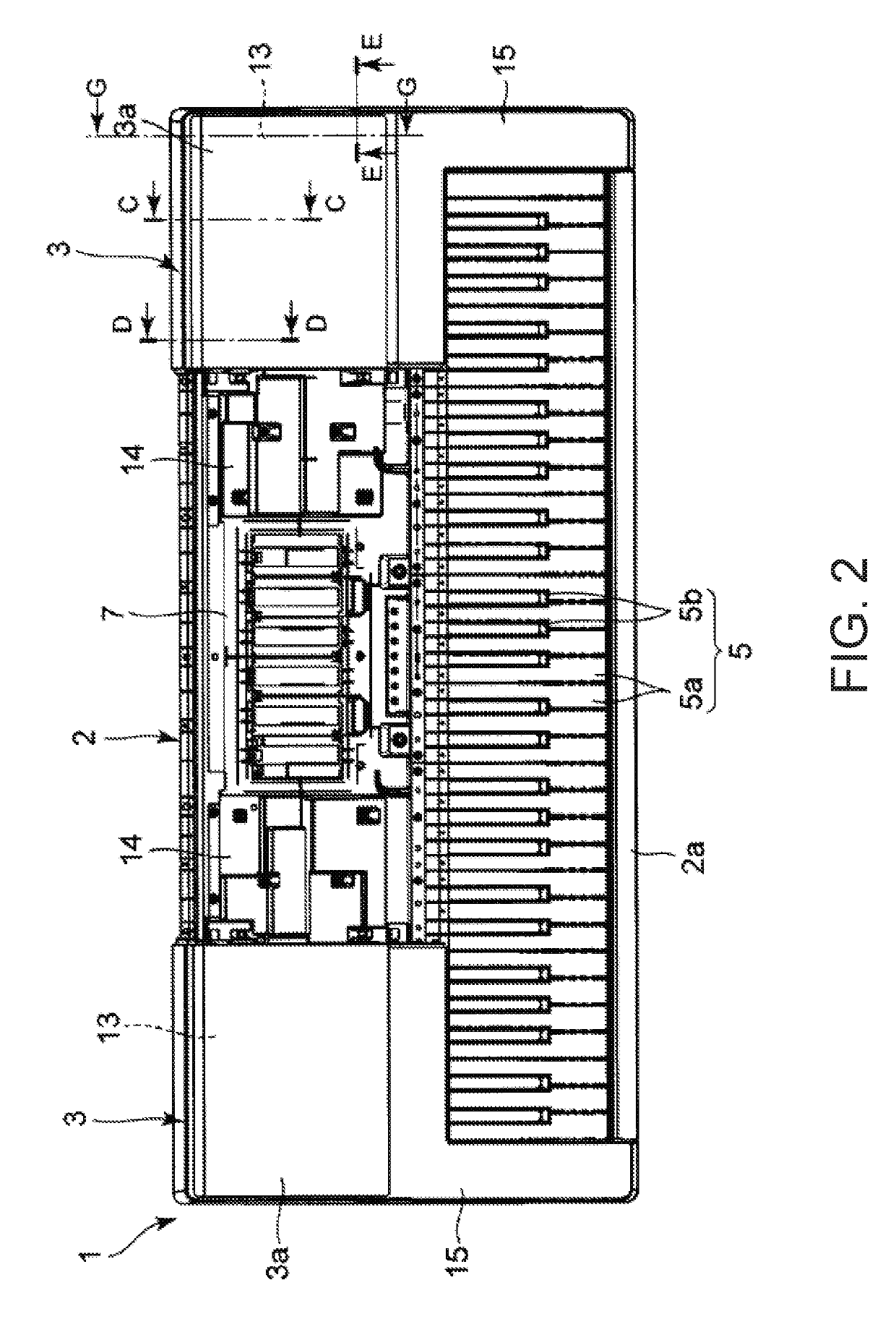
[0031]Next, an embodiment in which the present invention is applied to an electronic keyboard will be described with reference to FIGS. 1 to 14C.

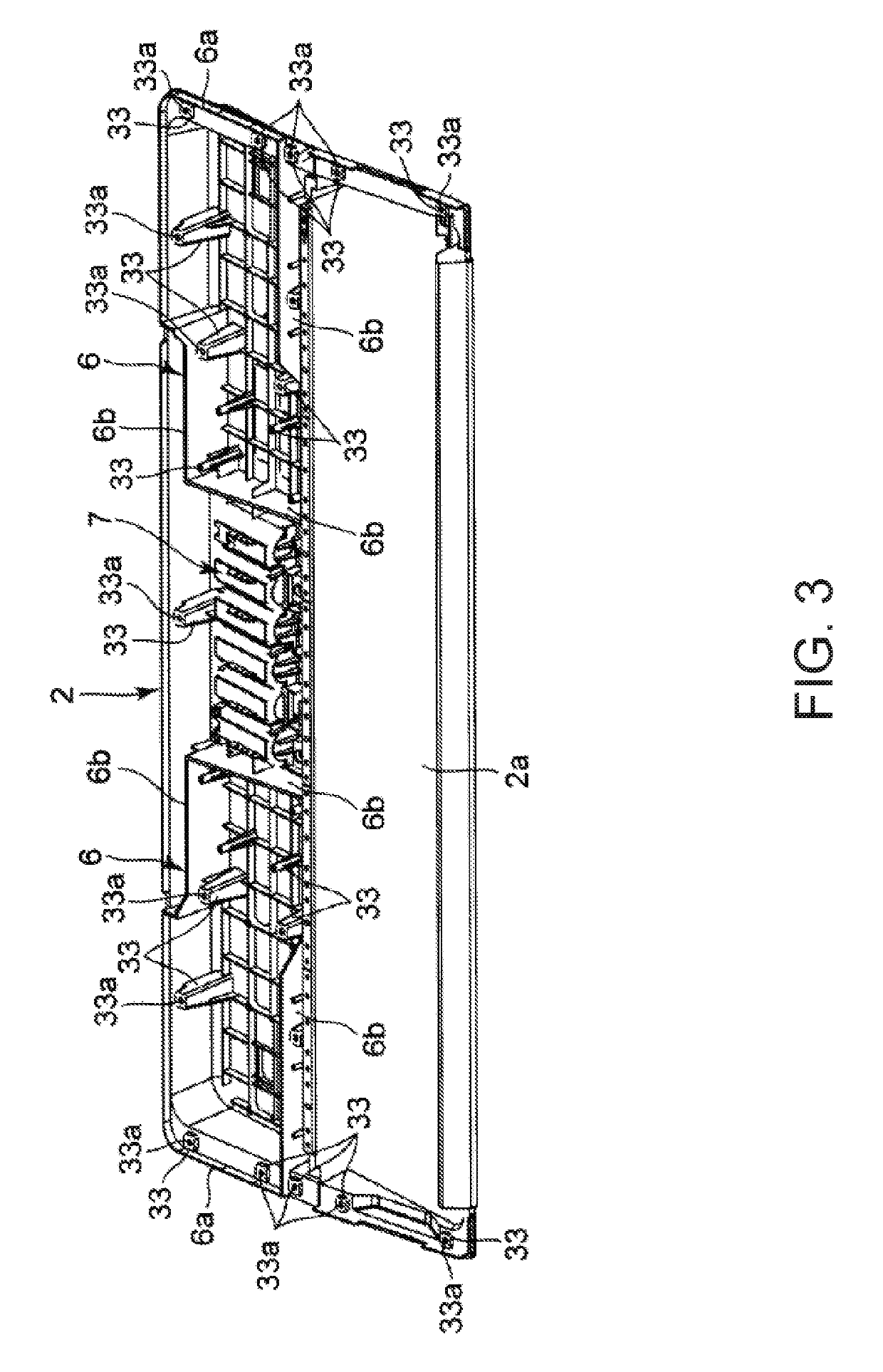
[0032]As illustrated in FIGS. 1 to 3, the electronic keyboard includes a musical instrument case 1. The musical instrument case 1 includes a lower case (bottom case) 2, upper cases (top cases) 3, and a center panel 4, and speaker boxes 1a are formed inside of these components.

[0033]As illustrated in FIG. 3, the bottom case 2 has a box shape that is open on the upper side and is elongated in the left-to-right direction. As illustrated in FIGS. 1 and 2, a keyboard mounting portion 2a for mounting a keyboard 5 is formed in the front side of the bottom case 2. The keyboard 5 includes white keys 5a and black keys 5b that are arranged along the lengthwise direction of the bottom case 2 on a keyboard chassis (not illustrated in the figures), and the keyboard chassis is mounted on the keyboard mounting portion 2a.

[0034]Moreover, as illustrated in ...


PUM


Abstract

A device case includes speaker boxes that are formed inside spaces created by placing upper cases that have a larger external shape than a lower case on upper of that lower case, as well as box connectors that are arranged fitting into the speaker boxes in the upper cases so as to contact the ends of peripheral portions of the lower case and fix together the lower case and the upper cases. This makes it possible for the box connectors to seal the spaces between the peripheral portions of the lower case and the peripheral portions of the upper cases. This, in turn, makes it possible to reliably and satisfactorily seal the speaker boxes in an airtight manner even when the external shapes of the lower case and the upper cases that are stacked together are different.

Description

BACKGROUND OF THE INVENTION1. Field of the Invention[0001]The present invention relates to a device case and a connector for use in an electronic device such as an electronic musical instrument or an audio device, and to an electronic musical instrument that includes the device case and connector.2. Description of the Related Art[0002]One well-known type of musical instrument case for an electronic musical instrument is that disclosed in Patent Document 1, for example, which includes a top case and a bottom case.[0003]In the top case, an upper box frame is arranged surrounding the upper sides of speakers, and in the bottom case, a lower box frame is arranged surrounding the lower sides of the speakers. Together, the upper box frame and the lower box frame form a speaker box.[0004]In Japanese Patent Application Laid-Open Publication No. 05-241574, the speakers are arranged in the rear corners on both sides of the top case. Therefore, the upper box frame of the speaker box includes a ...

Claims


Application Information

Patent Timeline
Patent Type & Authority Patents(United States)
IPC IPC(8): G10H1/32H04R1/02H04R1/28H04R1/24H04R1/26
CPCH04R1/24H04R1/2826G10H1/32H04R1/025H04R1/26G10H2230/365
Inventor HOSHINO, AKIHISA
Owner CASIO COMPUTER CO LTD
Why Eureka
Try Eureka