
Vacuum insulated switch-gear and its height adjusting method

a vacuum insulated switch and height adjustment technology, which is applied in the direction of high-tension/heavy-duty switch, substation/switching arrangement details, and arrangements with metal casings, etc., can solve the problems of dimensional error cannot be absorbed, the solid insulated bus bar having such a structure has no flexibility, and it is difficult to connect the solid insulated bus bar of the adjacent vacuum insulated switch gear to each other

Inactive Publication Date: 2012-11-06
HITACHI LTD
View PDF21 Cites 0 Cited by
  • Summary
  • Abstract
  • Description
  • Claims
  • Application Information

AI Technical Summary

Benefits of technology

The present invention proposes a vacuum insulated switch-gear with a height adjusting function and a method for adjusting the height of adjacent switch-gears. This allows for easy connection of solid insulated bus bars between adjacent switch-gears, even if there is a dimensional error between them. The height adjusting tool used for lifting up the switch-gear from the seating place can be easily carried out on-site, making the connection between bus bars possible. The technical effect of this invention is to simplify the process of connecting solid insulated bus bars between adjacent vacuum insulated switch-gears.

Problems solved by technology

The solid insulated bus bar having such a structure has no flexibility.
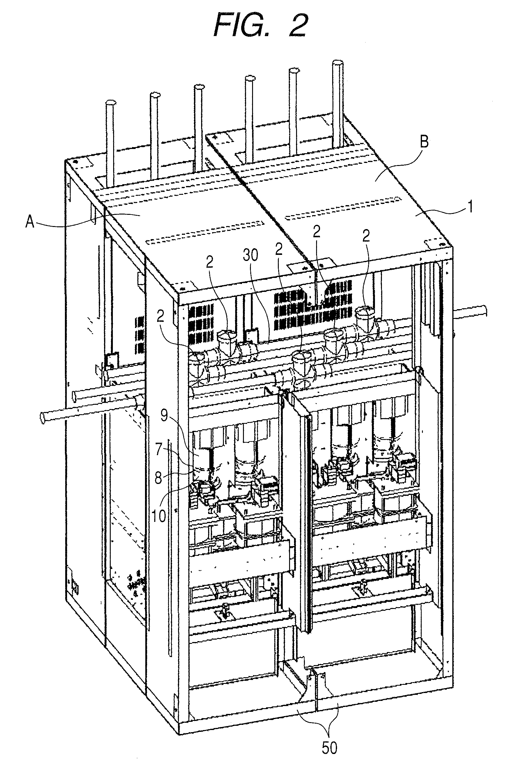
Therefore, in the case that a dimensional error between adjacent the vacuum insulated switch gears is caused in a vertical direction of them, for example, it caused by factors that the seating place on which each of the vacuum insulated switch gear seated is not flat or the switch gear has a dimensional error by itself in size thereof in manufacturing process, and so on, the dimensional error cannot be absorbed.
As a result, if there is the dimensional error between adjacent the vacuum insulated, it may be difficult to connect the solid insulated bus bars of the adjacent vacuum insulated switch-gears to each other.

Method used


Image

  • Vacuum insulated switch-gear and its height adjusting method
  • Vacuum insulated switch-gear and its height adjusting method
  • Vacuum insulated switch-gear and its height adjusting method

Examples


Embodiment Construction

[0030]Hereinafter, one embodiment of a vacuum insulated switch-gear related to the present invention is explained referring to drawings.

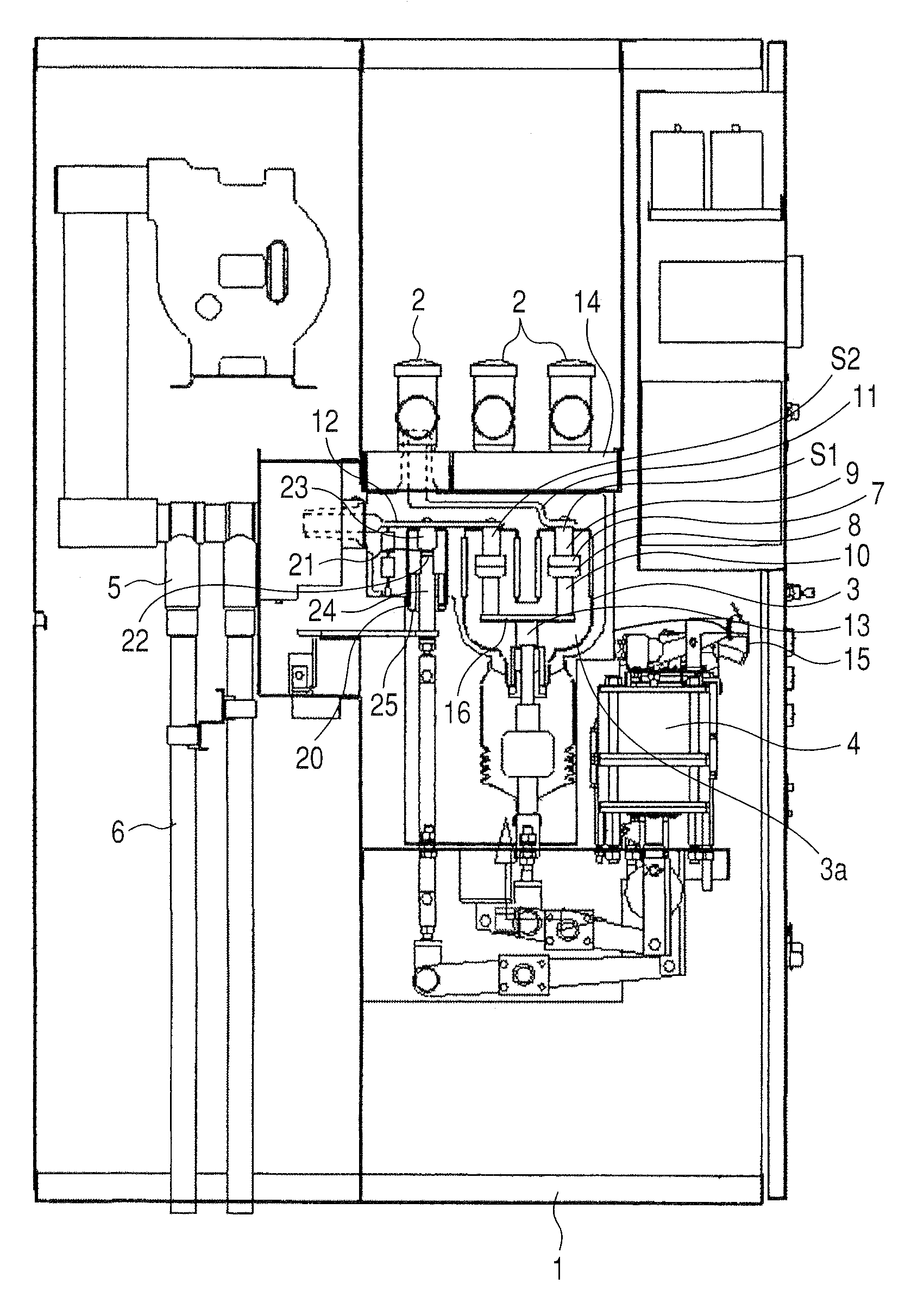
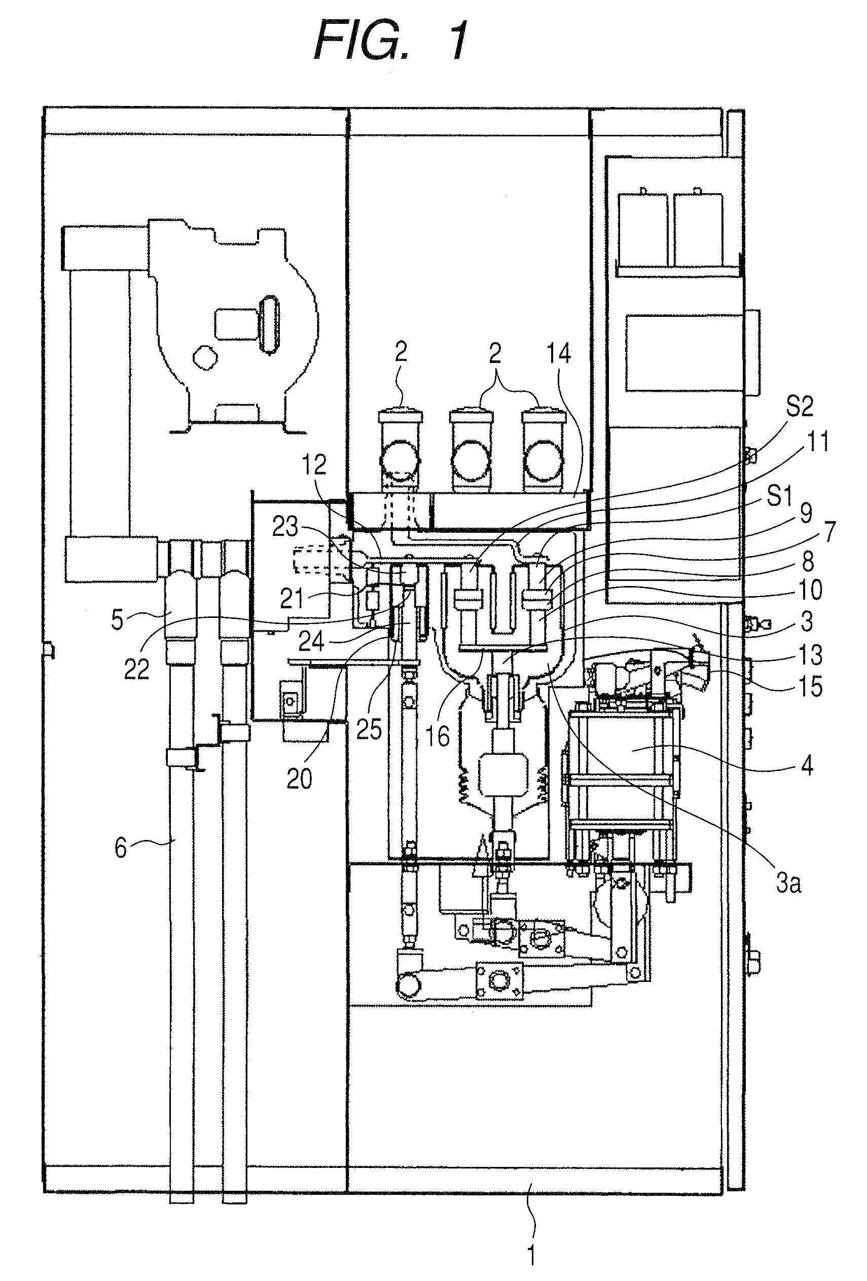
[0031]FIG. 1 shows a vacuum insulated switch-gear in accordance with the present invention. As shown in FIG. 1, the vacuum insulated switch-gear generally comprises a metal box 1 for accommodating components of the switch-gear, a vacuum valve 3 for each of three-phase (U, V and W phases), an earthing switch 20 for each of three-phase (U, V and W phases), tree-phase (U, V and W phases) bus bars 2 supplying electric power to the respective vacuum valves 3 and a cable 6 for each of three-phase (U, V and W phases) supplying the power to a load. Each vacuum valve 3 and each earthing switch 20 are accommodated within the metal box 1.

[0032]The vacuum valve 3 comprises two pairs of switch components S1 and S2 as a main circuit of the switch gear. One switch component S1 comprises a fixed electrode 7, a movable electrode 8 opposed to the fixed electrode 7, a...


PUM


Abstract

The vacuum insulated switch-gear is configured to be capable of being lifted up with a jack-up bolt to adjust a seated height of the vacuum insulated switch-gear. The switch-gear comprises a nut fixed on a base plate forming a bottom of the vacuum insulated switch-gear. The nut is used as a mating component with the jack-up bolt.

Description

CLAIM OF PRIORITY[0001]This application claims priority from Japanese application serial No. 2008-195611, filed on Jul. 30, 2008, the content of which is hereby incorporated by reference into this application.BACKGROUND OF THE INVENTION[0002]The present invention relates to a vacuum insulated switch-gear and its height adjusting method, and it is suitable to apply a vacuum insulated switch-gear assembly comprising plural vacuum insulated switch.[0003]A vacuum insulated switch-gear is highly regarded for realizing downsizing, easy maintenance, environmental load reduction and the like.[0004]A well-known vacuum insulated switch-gear is disclosed, for example, in a patent reference 1 (Japanese laid-open patent publication No. 2007-209077).[0005]In the reference 1, disclosed is a vacuum insulated switch-gear comprising a switch making interruption and disconnection functions, a main circuit forming the switch, a solid insulated bus bar connected with one end of the main circuit conducto...

Claims


Application Information

Patent Timeline
Patent Type & Authority Patents(United States)
IPC IPC(8): H01H33/66
CPCH01H33/66H02B1/303H01H2033/6665H02B13/02
Inventor KIKUKAWA, SHUICHITSUCHIYA, KENJIKAJIYAMA, YUKOSUGAI, DAISUKE
Owner HITACHI LTD
Learn More