Method for manufacturing a heat exchanger

a heat exchanger and manufacturing method technology, applied in the direction of manufacturing tools, light and heating equipment, laminated elements, etc., can solve the problems of deteriorating heat exchange performance, unfavorable variation in the distance between the plates, and the use of heat exchange fluid, so as to reduce the manufacturing cost of the heat exchanger, prevent abnormal increase in the temperature of the table, and control the consumption of energy

Inactive Publication Date: 2007-11-01
XENESYS
View PDF10 Cites 2 Cited by
  • Summary
  • Abstract
  • Description
  • Claims
  • Application Information

AI Technical Summary

Benefits of technology

[0012] An object of the present invention, which was made to solve the above-mentioned problems, is therefore to provide a method for manufacturing a heat exchanger, which enables a plurality of heat exchange plates as press-formed to be held in a stacked and aligned state so as to bring the portions of the heat exchange plates to be contacted into an appropriate contact with each other, thus making it possible to diffusion-bond in a subsequent step into a united body.
[0014] According to the first aspect of the present invention, the plurality of heat exchange plates as press-formed are placed on the table in the stacked and aligned state, and a pressing force is applied to the set of stacked plates in the stacking direction in such a state. In addition, a space surrounding the plates is put in a condition where pressure is reduced in a vacuum or low-pressure state in which the diffusion bonding can be carried out. It is therefore possible to bring accurately the portions to be contacted of the stacked plates into a proper contact with each other. The stacked plates can appropriately be diffusion-bonded into a united body in the subsequent step in a state in which the portions to be contacted of the stacked plates are brought into contact with each other. It is therefore possible to manufacture the heat exchanger, which has many bonded points of the plates to enhance strength and pressure-resistant property, by utilizing the heat exchange plates as press-formed having a complicated configuration. Thus, performance of the heat exchanger can therefore be enhanced.
[0016] According to the second aspect of the present invention, the set of stacked heat exchange plates is put into the tubular shell and the air-tight property is maintained at connection portions between the opposite ends of the shell and the table and pressing member, respectively. In such a state, removal of gas from the space surrounding the plates puts the whole inner region defined by the shell into a vacuum or low-pressure state. The space surrounding the contact portions of the plates can surely be put into the vacuum or low-pressure state, along with a contractible deformation of the shell, to improve reliability in the diffusion bonding process, thus providing a sure bonding of the plates. In addition, it is possible to minimize the space, which surrounds the plates and is subjected to removal of air or pressure reduction, to reduce costs required for adjusting a surrounding atmosphere of the plates in a state in which the diffusion bonding process can be carried out. Further, the diffusion bonding process can easily be performed.
[0018] According to the third aspect of the present invention, the power supply is connected to the set of stacked heat exchange plates through the cables. Application of an electric current to the heat exchange plates causes the temperature of the respective plates to directly increase by Joule heat of the plates themselves to reach a temperature at which the diffusion bonding occurs. There is no need to increase the temperature of the space surrounding the plates for the heating of the plates during the diffusion bonding process. It is therefore possible to carry out simply the diffusion bonding step, without providing any additional large-scaled facilities, thus controlling consumption of energy and reducing manufacturing costs of the heat exchanger.
[0019] In the fourth aspect of the method of the present invention for manufacturing the heat exchanger, the table and / or the pressing member may be put in a state in which a heat transmission is caused between the heat exchange plates and the table and / or pressing member, the table and / or the pressing member having a hollow portion, which is connected to fluid conduits for supplying a cooling fluid into the hollow portion and discharging same therefrom, to cause the cooling fluid to flow in the hollow portion, thereby cooling the heat exchange plates and the table and / or pressing member.
[0020] According to the fourth aspect of the present invention, the table and / or the pressing member that are placed on the outer sides of the set of stacked heat exchange plates has the hollow portion through which the cooling fluid flows. Causing the cooling fluid to flow in the hollow portion during the diffusion bonding process or after completion thereof permits to cool not only the table and / or the pressing member, but also the heat exchange plates, which have a heat transmission property, in an active manner. It is therefore possible to prevent abnormal increase in temperature of the table and / or the pressing member during the diffusion bonding process. In addition, it is possible to decrease a period of time when the plates as diffusion-bonded are kept in a high temperature condition, which may easily cause variation in characteristic properties of the plates, to prevent unfavorable variation in characteristic properties of the plates. Thus, the diffusion bonding process can safely be carried out and performance and reliability of the heat exchanger as manufactured can be improved.

Problems solved by technology

However, a high pressure of the heat exchange fluid flowing between the plates may cause deformation of the gasket member, thus disabling an appropriate separation of the fluids from being ensured or leading to an unfavorable variation in distance between the plates.
In such a case, an effective heat exchange may not be carried out, thus causing a problem.
In view of these facts, the conventional heat exchanger involves a problem that the heat exchange fluids can be utilized only in a pressure range in which the gasket member withstands.
As a result, difference in pressure between heat exchange fluids flowing along the respective opposite surfaces of the plates becomes larger, the distance between the adjacent plates at a non-bonded portion such as a central portion may vary, not only deteriorating heat exchange performance, but also leading to damage of the heat exchanger.
Therefore, such a heat exchanger may not be used under a relatively high pressure condition.
However, in the plates of such plate-type heat exchangers, which include the heat exchanger described in Japanese Patent Provisional Publication No. 2003-194490, in which the plates that have a complicated pattern of irregularity formed by a press forming process come into contact with each other at projection portions thereof in a stacked state, it is difficult to maintain an accurate flatness in a general surface of the plates as press-formed.
In addition, when a large pressing force is applied to the plate, the plate may easily be deformed.
It is therefore difficult to bring the portions of the plates to be contacted, at the projection portions thereof, into a proper contact with each other, merely by placing the plates one upon another, thus causing problems.
Therefore, it is not possible to utilize, without any modification, the technical matters described in Japanese Patent Publication No.

Method used


Image

  • Method for manufacturing a heat exchanger
  • Method for manufacturing a heat exchanger
  • Method for manufacturing a heat exchanger

Examples


Embodiment Construction

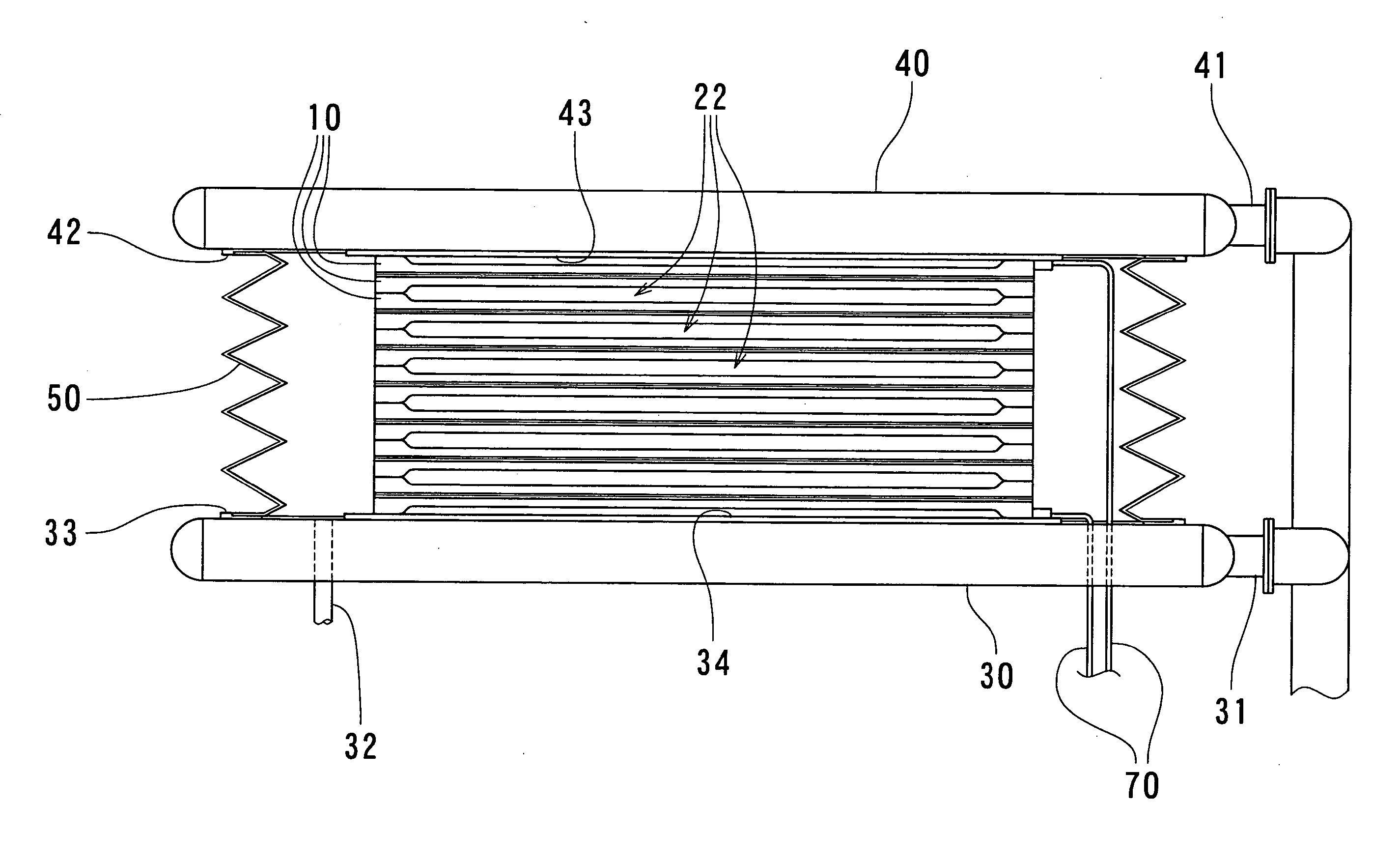
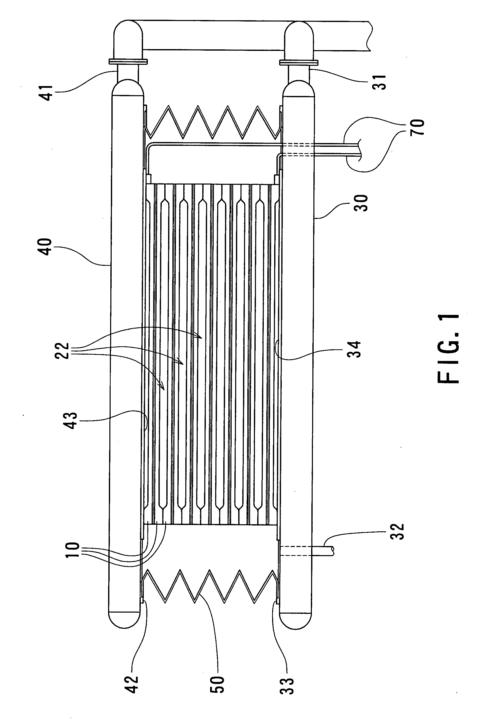
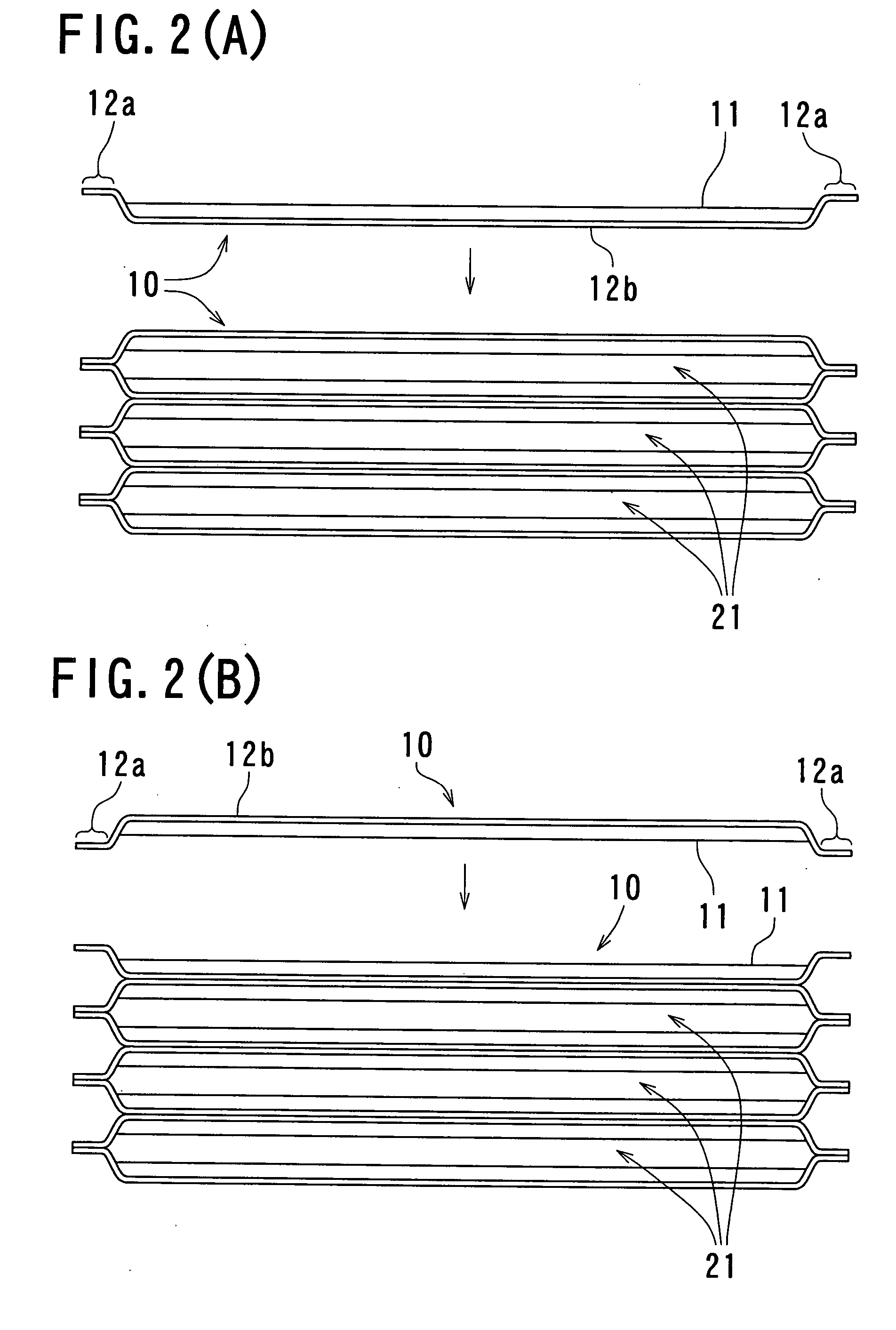
[0026] Now, the embodiment of the present invention will be described in detail below with reference to FIGS. 1 to 5. FIG. 1 is a schematic structural view illustrating a state in which a pressing force is applied to a set of stacked heat exchange plates prior to a diffusion bonding process in a heat exchanger manufacturing method according to an embodiment of the present invention, FIGS. 2(A) and 2(B) are descriptive views illustrating a stacking state of heat exchange plates in the heat exchanger manufacturing method according to the embodiment of the present invention, FIG. 3 is a descriptive view illustrating a step for placing the set of stacked heat exchange plates on a table in accordance with the heat exchanger manufacturing method according to the embodiment of the present invention, FIG. 4 is a descriptive perspective view illustrating a state in which the set of stacked heat exchange plates is placed on the table in accordance with the heat exchanger manufacturing method ...


PUM

PropertyMeasurementUnit
shapeaaaaaaaaaa
pressing forceaaaaaaaaaa
electric currentaaaaaaaaaa

Abstract

Heat exchange plates are stacked. The stacked plates are transported to a table. A pressing member is placed on an uppermost plate of the stacked plates to apply a pressing force to them. A shell is placed to surround a space encompassing the stacked plates to isolate the plates from an outside. A gas is discharged from the space encompassing the plates to the outside through gas supply / discharge sections provided on the table.

Description

BACKGROUND OF THE INVENTION [0001] 1. Field of the Invention [0002] The present invention relates a method for manufacturing a heat exchanger in which a plurality of heat exchange plates each made of a thin metallic plate are combined in parallel and integrally with each other, and especially to a method for manufacturing such a heat exchanger, which enables, prior to subjecting the heat exchange plates to a diffusion bonding process to form a united body, contact portions of the heat exchange plates as stacked to be kept in an appropriate contact state to ensure a subsequent bonding step in an appropriate manner. [0003] 2. Description of the Related Art [0004] If there is a demand that heat transfer coefficient is increased to enhance heat exchange efficiency, utilizing a heat exchanger by which transfer of heat (i.e., heat exchange) is made between a high temperature fluid and a low temperature fluid, a plate-type heat exchanger has conventionally been used widely. The plate-type ...

Claims


Application Information

Patent Timeline
Patent Type & Authority Applications(United States)
IPC IPC(8): B23K11/00
CPCB23K20/02B23K20/14F28F2275/061F28D9/0037B23K2201/14B23K2101/14F28D9/00F28F3/00
Inventor MATSUZAKI, TOYOAKI
Owner XENESYS
Why Eureka
Try Eureka