Structure for connecting flexible flat cables

a technology of flexible flat cables and cables, applied in the direction of flat/ribbon cables, fixed connections, coupling device connections, etc., can solve the problem that the connection member cannot be electromagnetically shielded

Pending Publication Date: 2021-08-12
AUTONETWORKS TECH LTD +2
View PDF17 Cites 0 Cited by
  • Summary
  • Abstract
  • Description
  • Claims
  • Application Information

AI Technical Summary

Benefits of technology

[0018]According to the technology disclosed in this specification, it is possible to connect a plurality of flexible flat cables having electromagnetically shielded conductive paths.

Problems solved by technology

When flexible flat cables that have such a shielding structure are to be connected to each other, if a method is adopted in which a connection member is inserted in a state in which a plurality of flexible flat cables are vertically placed on each other as in conventional technology, an issue arises that the connection member cannot be electromagnetically shielded because the connection member is not enclosed by the shield layer.

Method used


Image

  • Structure for connecting flexible flat cables
  • Structure for connecting flexible flat cables
  • Structure for connecting flexible flat cables

Examples


embodiment 1

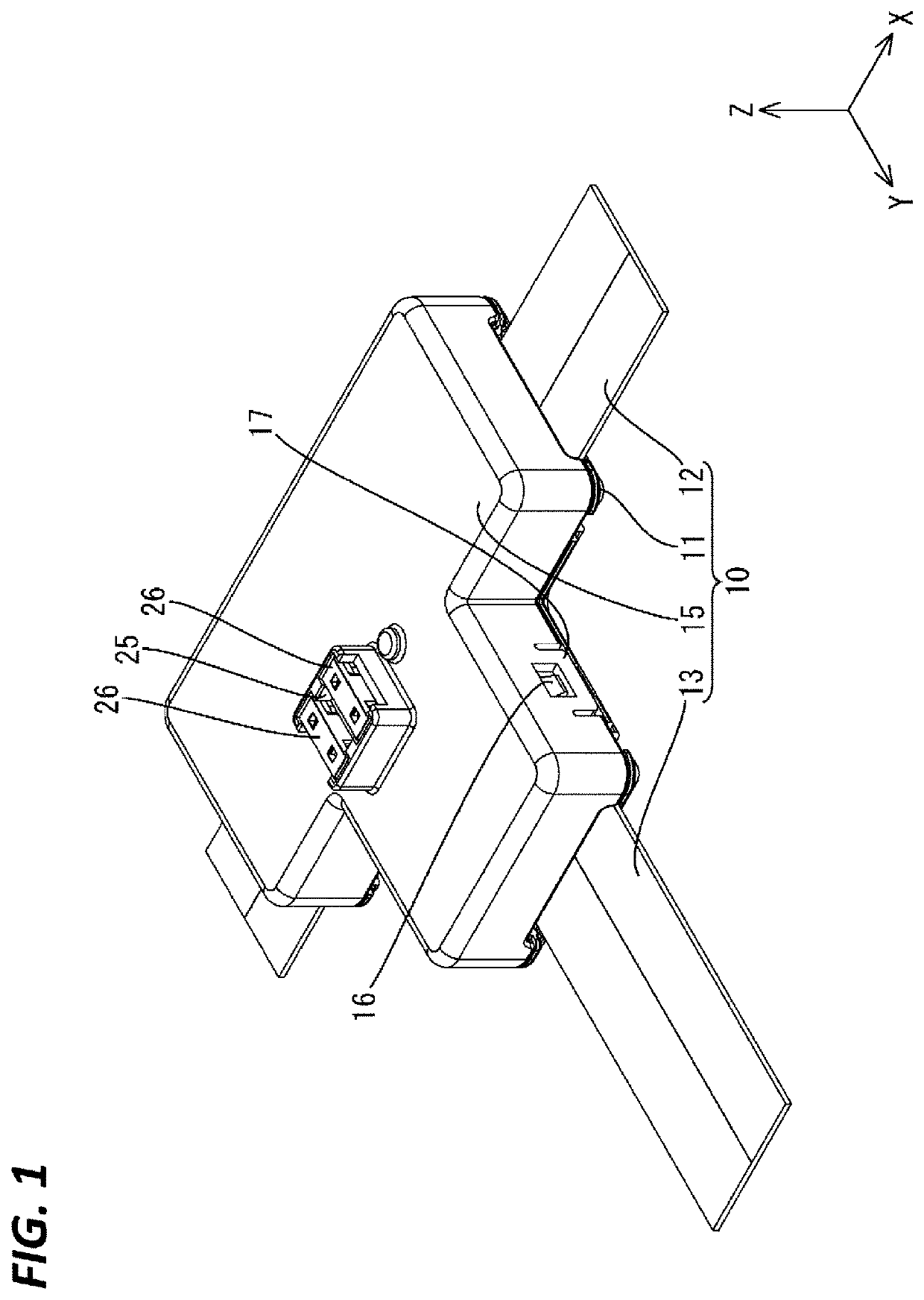
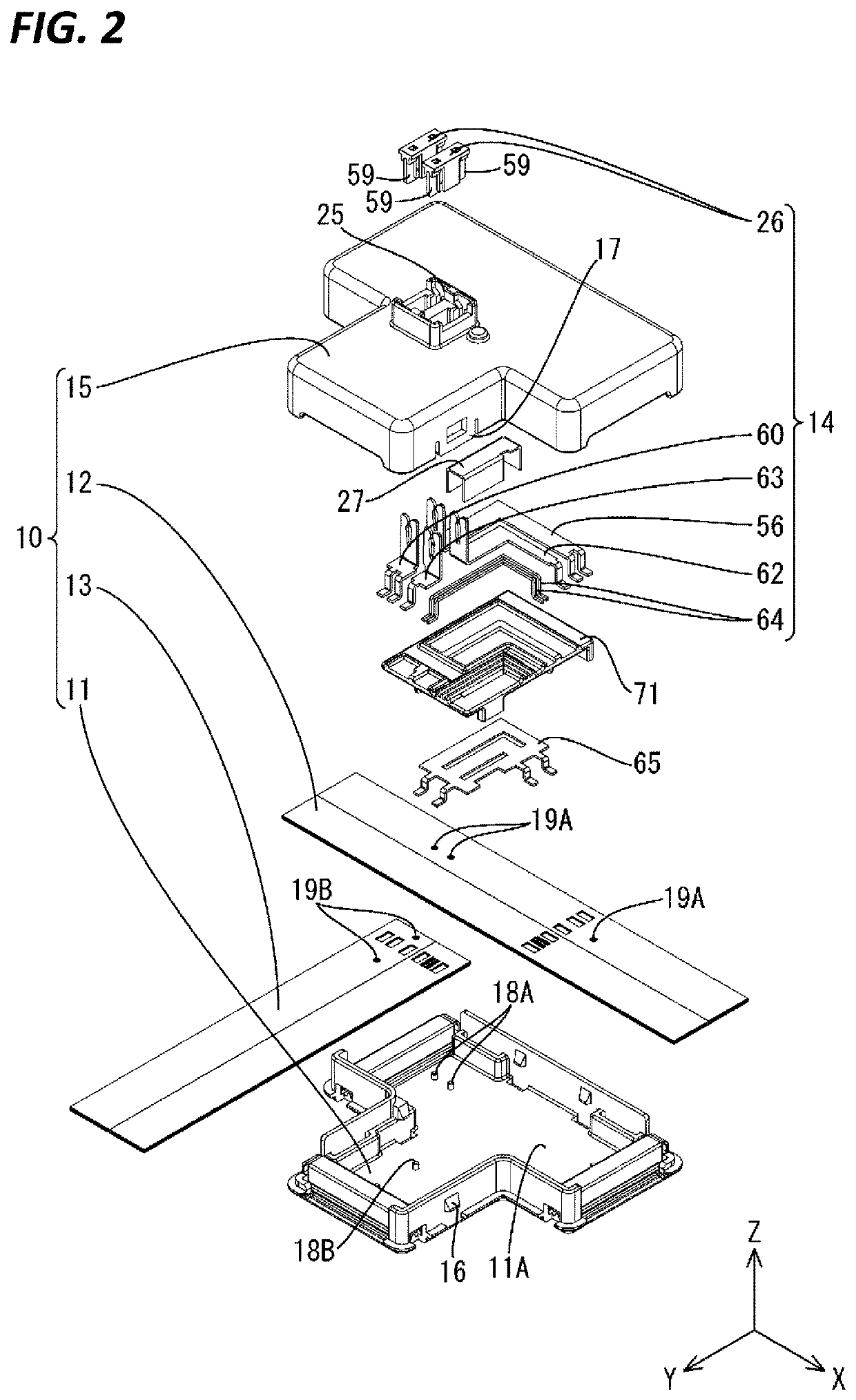
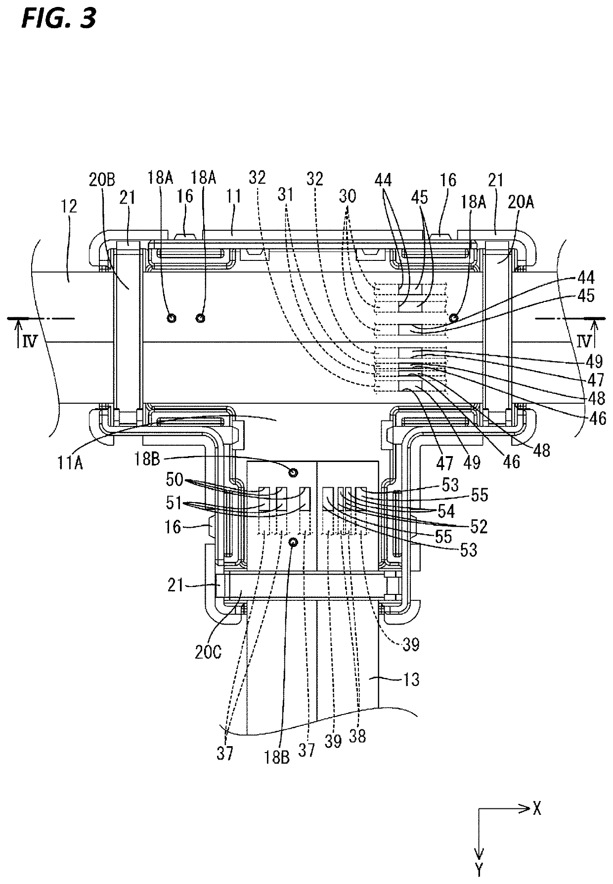
[0052]Embodiment 1 of technology disclosed in this specification will be described with reference to FIGS. 1 to 17. A branch box 10 according to this embodiment includes a case 11, a trunk cable 12 (an example of a flexible flat trunk cable) fixed to the case 11, a branch cable 13 (an example of a flexible flat branch cable) fixed to the case 11, a conductive relay path 14 for electrically connecting the trunk cable 12 and the branch cable 13, and a cover 15 mounted on the case 11. The branch box 10 is installed in a vehicle (not shown) such as an electric car or a hybrid automobile, for example, and branches a power circuit and a signal circuit. In the following description, “upper” refers to the Z-direction, “front” refers to the Y-direction, and “left” refers to the X-direction. Note that, with regard to a plurality of the same members, only some of the same members may be given reference numerals, and the other members may not be given reference numerals.

[0053]Branch Box 10

[0054...

embodiment 2

[0156]Next, a branch box 80 according to Embodiment 2 of technology disclosed in this specification will be described with reference to FIGS. 18 to 25.

[0157]Cover 81

[0158]As shown in FIG. 19, a trunk operation hole 82 that extends in the front-rear direction passes through a region at a rear portion of the upper wall of a cover 81, the region extending in the right-left direction and being located slightly on the left side of this rear portion. The trunk operation hole 82 has a rectangular shape when viewed from above. A hole edge portion of the trunk operation hole 82 can be regarded as a frame portion 83 that protrudes slightly upward from the upper wall of the cover 81. A front end portion of the frame portion 83 is provided with a subcover locking reception portion 85 that protrudes forward and to which a subcover locking claw 84, which will be described, is locked.

[0159]A rear end portion of the trunk operation hole 82 is provided, as a single body with the cover 81, with a sub...

embodiment 3

[0190]Next, Embodiment 3 of technology disclosed in this specification will be described with reference to FIGS. 26 to 29.

[0191]As shown in FIG. 27, an insulating plate 110 is made of an insulating synthetic resin, and has a substantially rectangular shape when viewed from above. The insulating plate 110 includes an insulating plate-side first slit 74 that is bent in an L-shape when viewed from above, and an insulating plate-side second slit 75 that is located on the left side of the insulating plate-side first slit 74 and extends in the front-rear direction when viewed from above.

[0192]A first trunk-side bus bar 56, a first branch-side bus bar 60, a second trunk-side bus bar 62, a second branch-side bus bar 63, and relay bus bars 64 are arranged on the upper side of the insulating plate 110. The upper side of the insulating plate 110 is provided with multiple lines of ribs 72 that protrude upward. The first trunk-side bus bar 56, the first branch-side bus bar 60, the second trunk-s...


PUM

PropertyMeasurementUnit
flexibleaaaaaaaaaa
insulatingaaaaaaaaaa
flexibilityaaaaaaaaaa

Abstract

A trunk cable 12 includes a signal trunk conductor 31 that is electromagnetically shielded by a shield layer 35. A branch cable 13 includes a signal branch conductor 38 that is electromagnetically shielded by a shield layer 42. The signal trunk conductor 31 and the signal branch conductor 38 are electrically connected to each other by a relay bus bar 64 that is electromagnetically shielded by a base shielding member 65 and a cover shielding member 27.

Description

TECHNICAL FIELD[0001]Technology disclosed in this specification relates to a structure for connecting a plurality of flexible flat cables.BACKGROUND[0002]Conventionally known is a flexible flat cable that has a conductive path and a flexible insulating layer enclosing the conductive path. Because this flexible flat cable has flexibility, it is possible to suitably use the flexible flat cable if wiring is required in a limited space such as in a vehicle, for example.[0003]The technology disclosed in Japanese Patent Laid-Open Publication No. 2003-168508 is known as technology for connecting a plurality of flexible flat cables. According to this technology, a conductive path of a lower flexible flat cable and a conductive path of an upper flexible flat cable are electrically connected to each other by a connection member by inserting the connection member in a state in which a plurality of flexible flat cables to be connected to each other are vertically placed on each other.PRIOR ART ...

Claims


Application Information

Patent Timeline
Patent Type & Authority Applications(United States)
IPC IPC(8): H01R12/61H01R13/688B60R16/023H01B7/08H02G15/08
CPCH01R12/613H01R13/688H02G15/08H01B7/08B60R16/023H02G15/113B60R16/0215
Inventor YAMAMOTO, SATOSHIHIRAI, HIROKIHIGASHIKOZONO, MAKOTOOHARA, KAZUYOSHISAWADA, HISASHI
Owner AUTONETWORKS TECH LTD
Why Eureka
Try Eureka